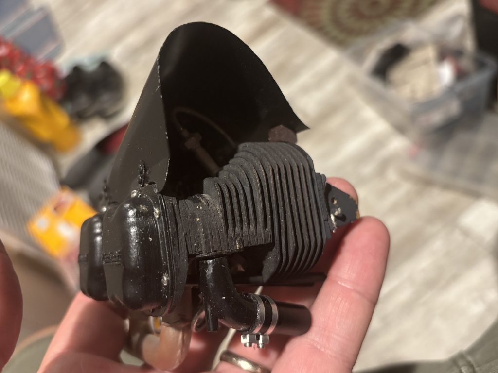
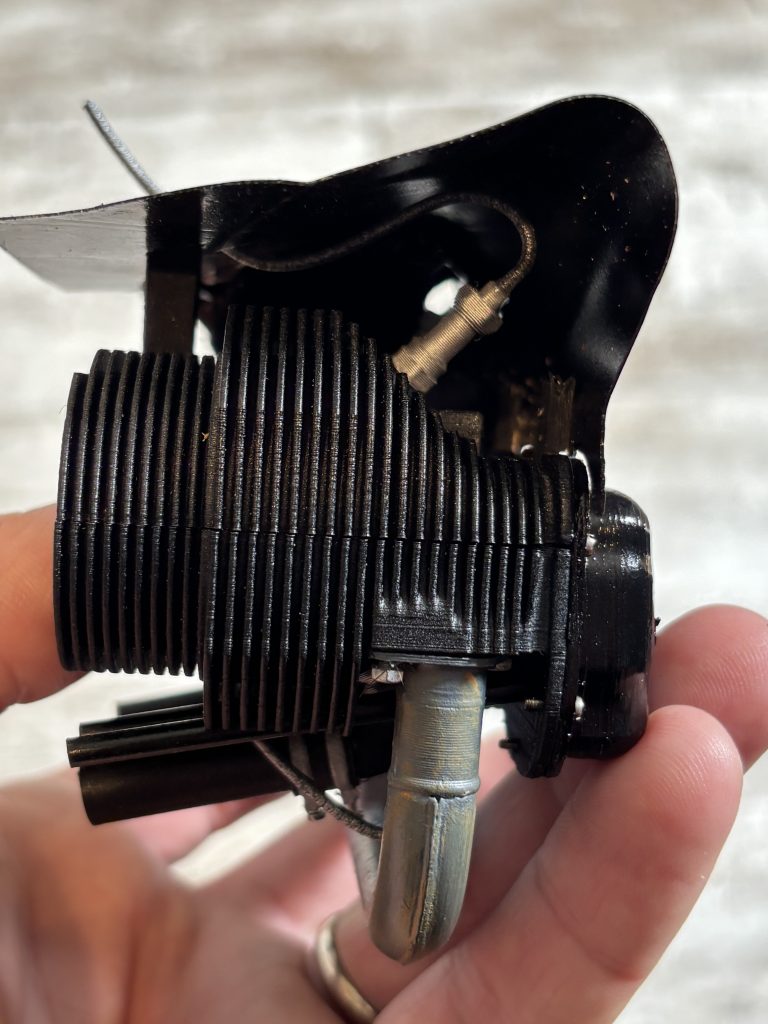
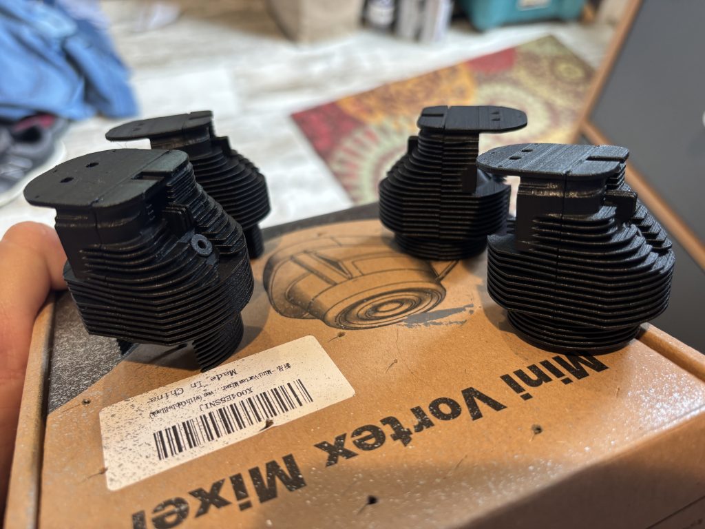
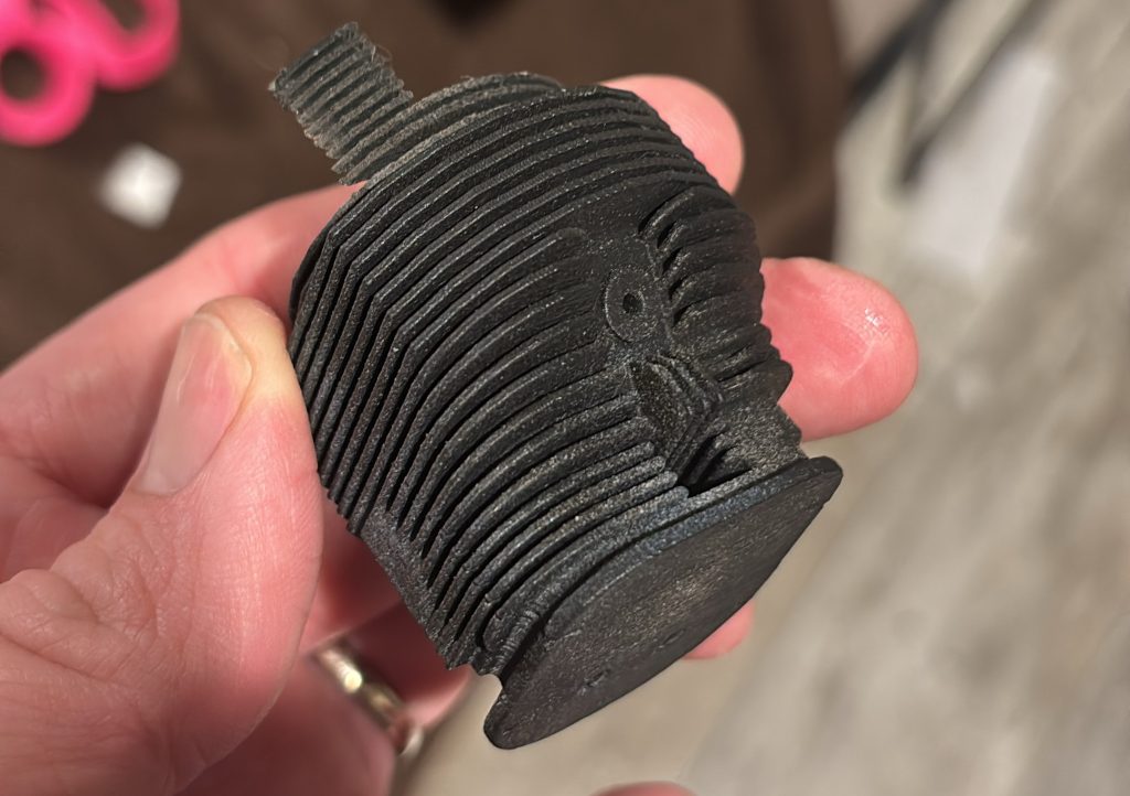
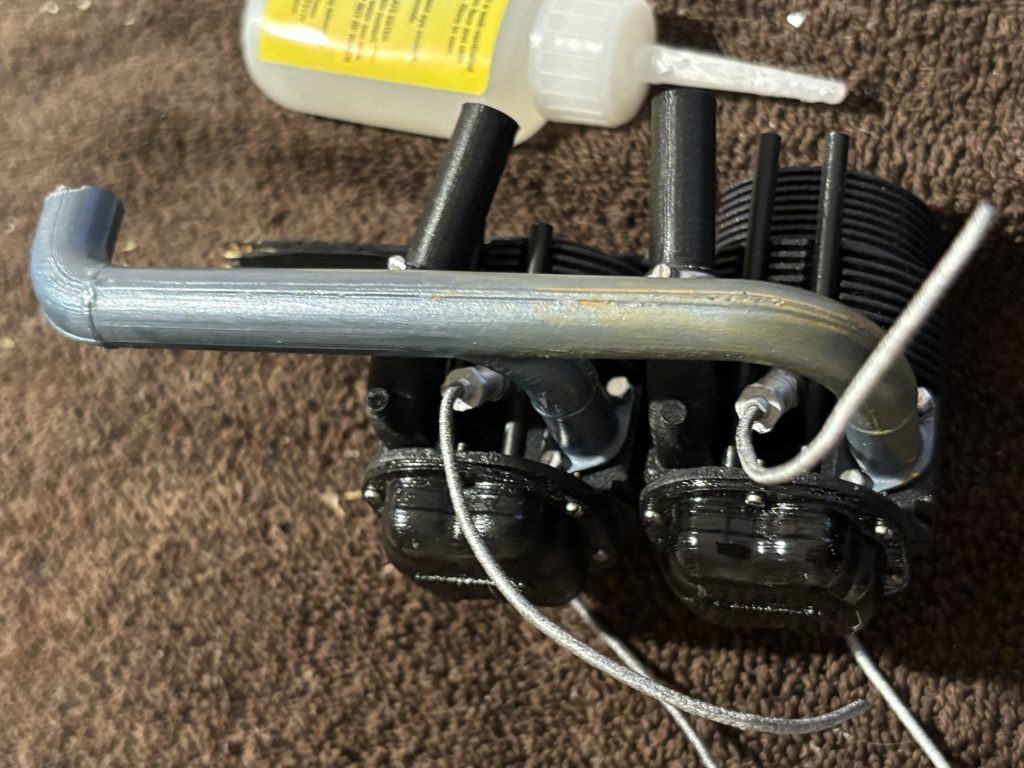
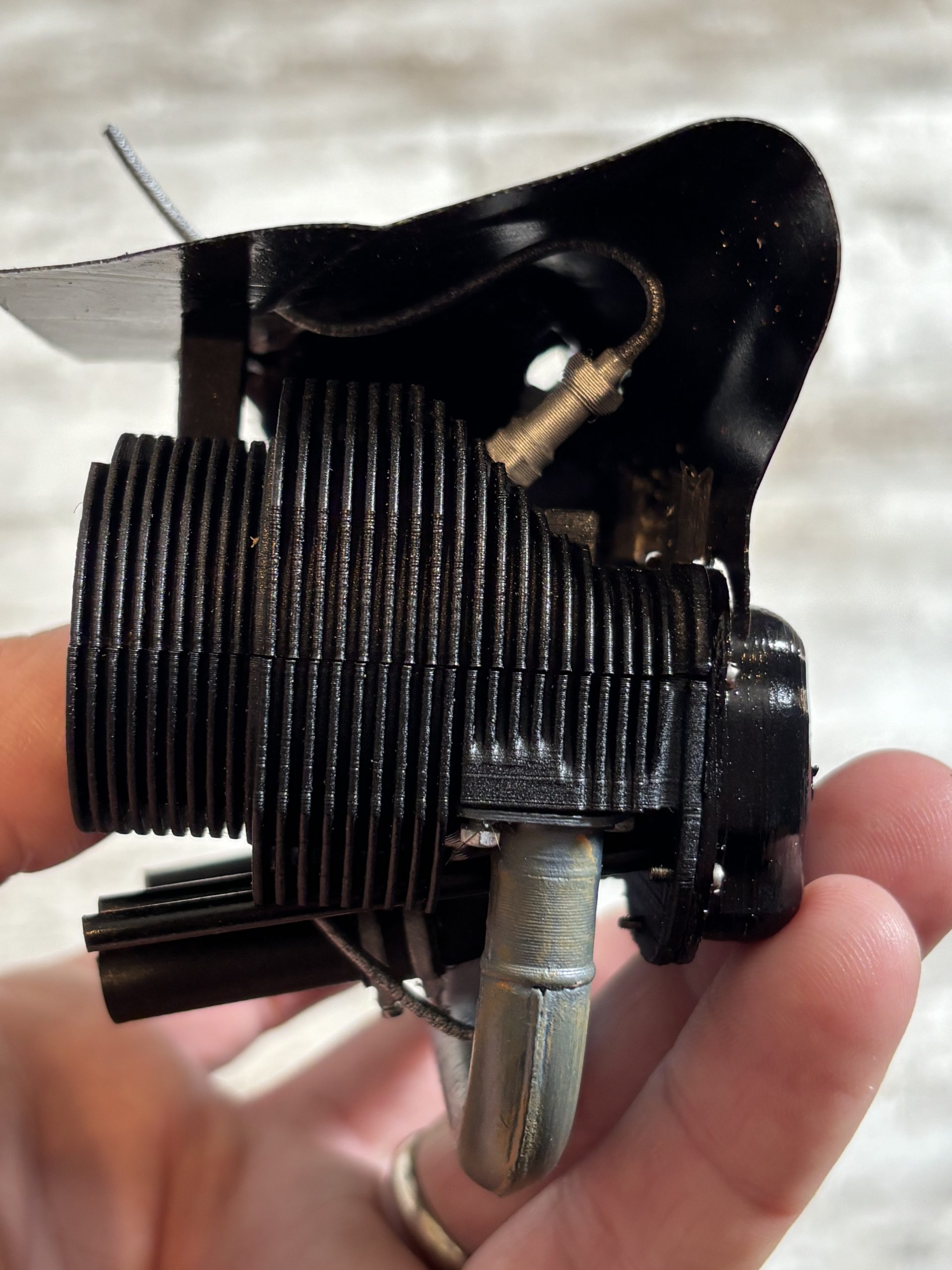
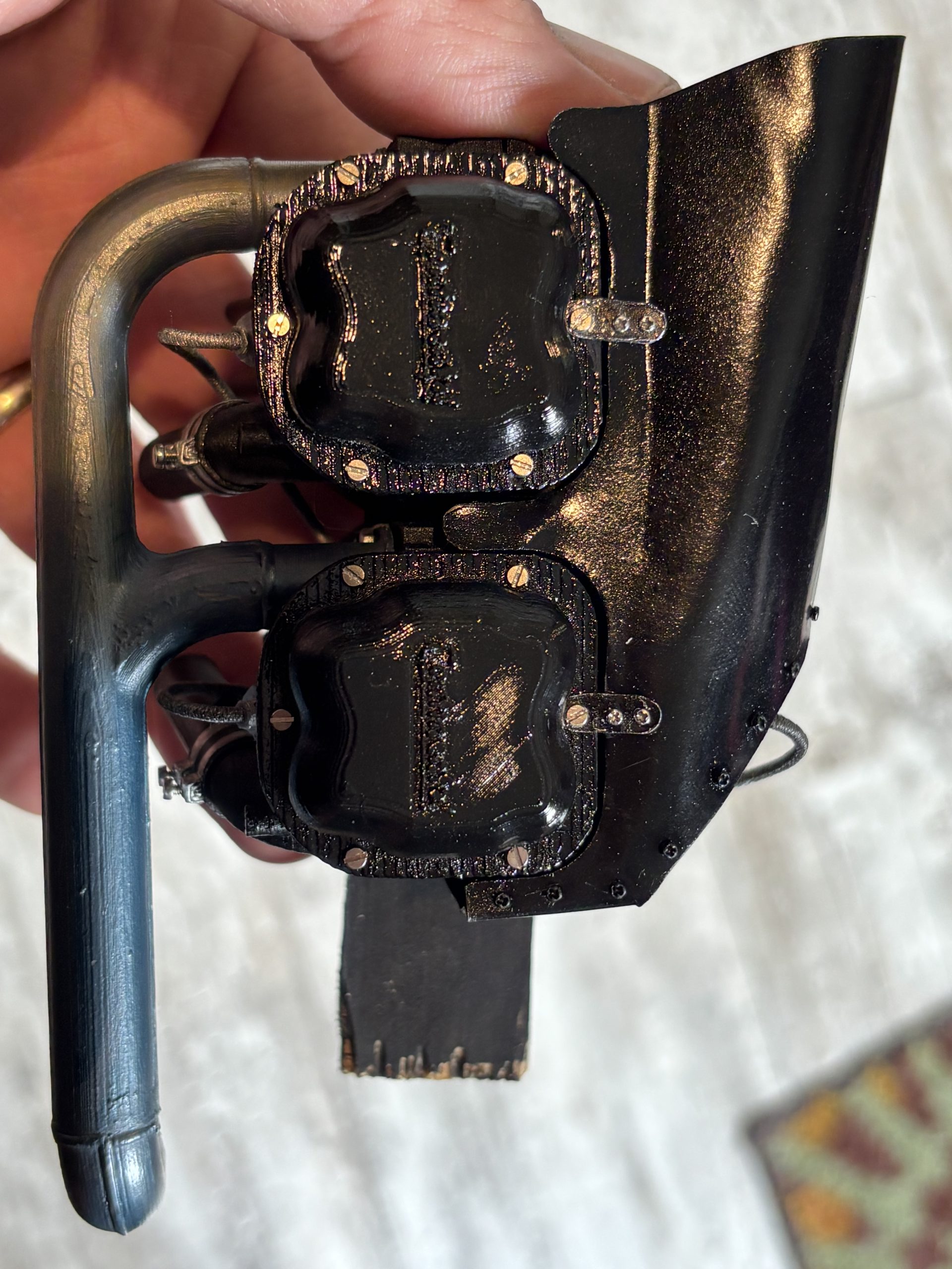
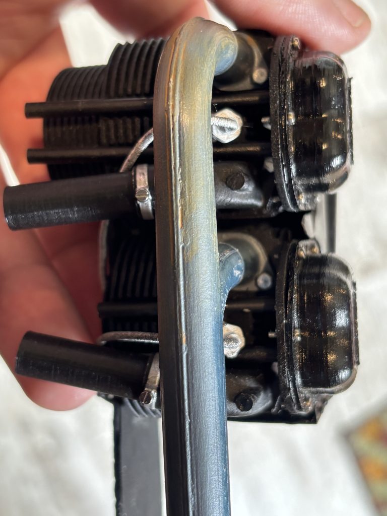
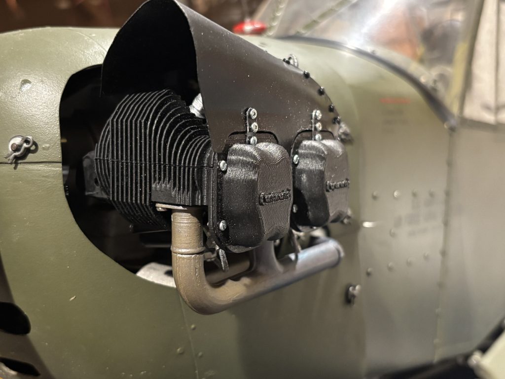
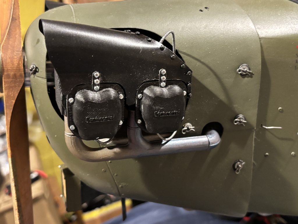
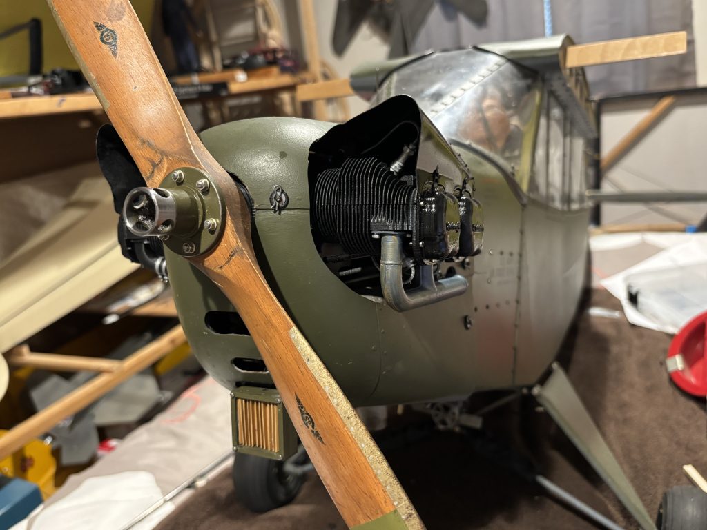
The most detailed and accurate scale Continental Engine you will find on the market. This is a Scale Masters \ TopGun level of a kit. I have spent hours on the development of this kit. I would say over 90 percent of this build has come from full scale prints along with photos I have taken. All the fin outlines were traced from a full-scale photo. Some areas like fin thickness are a little off to make a sturdier build.
As with all my pages, I recommend reading through the full page before starting the project. This will give you an idea of where we are going before you get to that part of the project. Feel free to contact me with any questions or suggestions.
This is all centered around the 1/4 scale Cub. I will be soon updating it with 1/3 scale info also. 1/4 is as small as I Can comfortably go down to and have a reliable product. If you need something larger than 1/4 or 1/3 scale, contact me and see what we can work out.
What’s in the box and what will you need to finish this build to scale your cub out.
In the box.
4 cylinders (8 parts)
4 valve covers
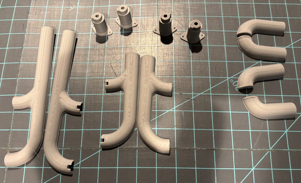
Exhaust system (12 parts)
Tubing for pushrod sleeves.
8 sparkplugs.
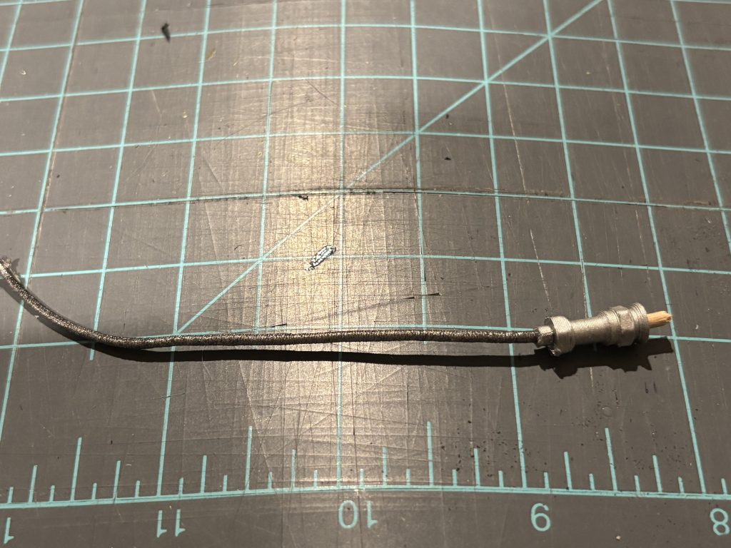
Cord for plug wires.
Oil cap and tube
16 hex head bolts
40 M1 screws
26 M1.4 cheese head screws
Aluminum sheet for eyebrows
What you will need.
Tools
Small straight and phillips screwdrivers.
Hobby knife
Tin snips
Dremel with sanding drum and cutoff wheel
Ruler
Hemostats
Laser level
Bubble level
Magnet parts tray
Small detail paint brushes
Hand drill with the following bit size.
For 1/4 scale
.028 (pilot holes for eyebrows)
1/32 (Holes for valve covers screws)
1/16 (plug wires and valve cover holes)
3/32 (holes for header bolts and toothpicks)
1/8 (push rod openings)
Supplies
Medium and thin CA glue with kicker
Testors Contour Putty
Sharpy fine tip marker
Wood for making the mounts.
For 1/4 scale
1/4 ply
1/16 ply
1/4 hard and soft balsa
1/16 x 3/16 spruce or hard wood
1/32 x 3/16 spruce or hard wood
Paint Below is suggestions but may be different based on the full-scale model you are using. May not need all of them depending on how scale you want to go.
Spray-paint.
Black (Gloss, semigloss, Matt, or flat depending on your look of the full-scale)
Aluminum
Matt clear coat
Gray Primer
Other colors depending on your full-scale model.
Brush Paint ( I like Vallejo Acrylic paint)
Magic Blue
Bloody Red
Oily Steel
Gunmetal Blue
Yellowish rust
Black Gray
Black Mat
Black Gloss
White Gloss
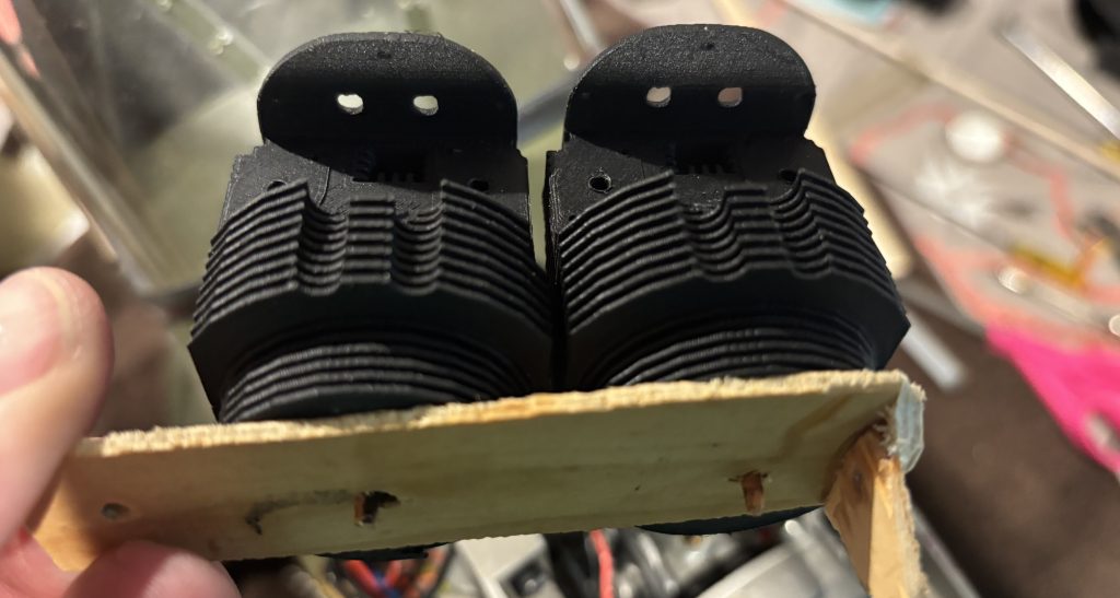
A big improvement as the old setup was layers of balsa and light ply that had to be cut, a lot of the parts were form in a mold. The new is all 3d printed. The old setup weighed in at 5.1 oz the new is 6 oz so not much more weight gain. Old on the left, new on the right.
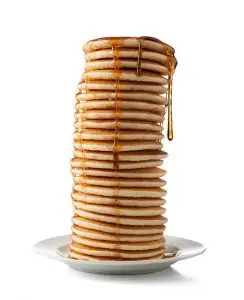
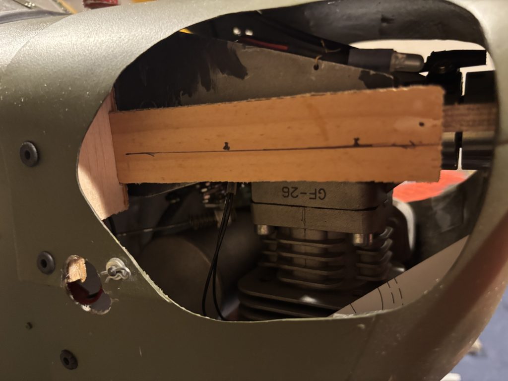
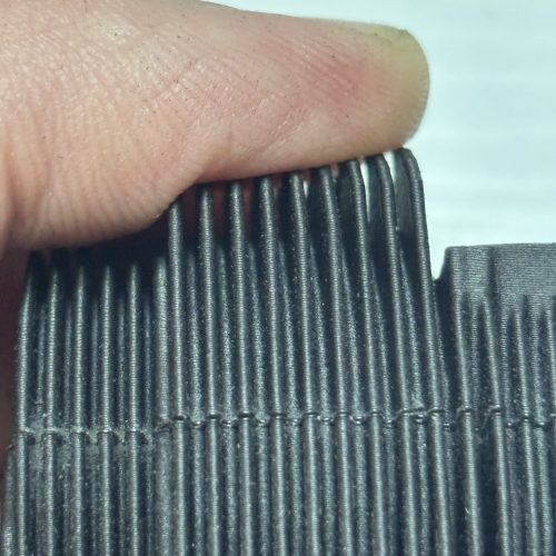
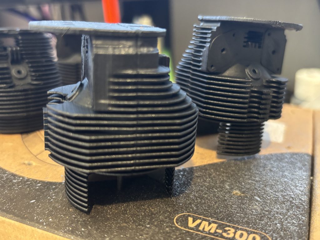
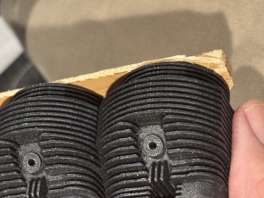
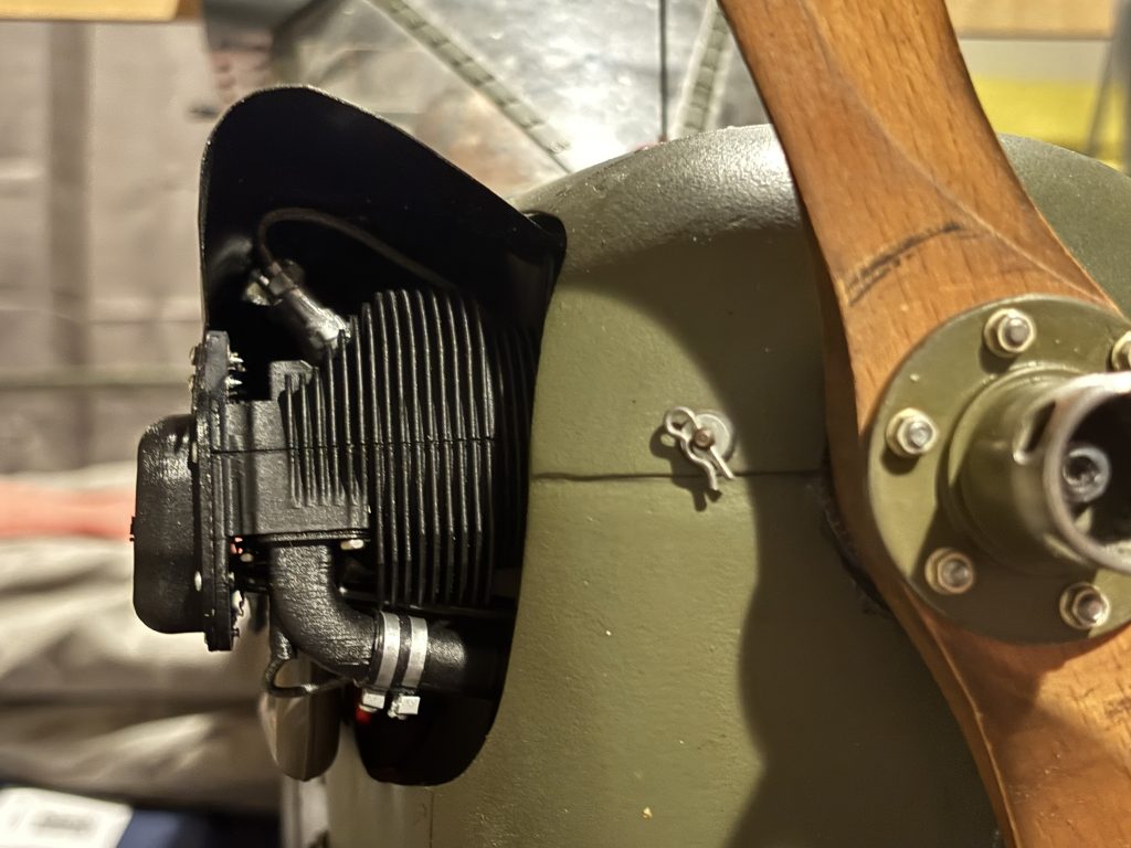
Just a little info on 3D printed objects. Items are built up of many layers of filament stacked up like a stack of pancakes. Most all our items will be printed on a .20mm layer, so each layer is .20 mm high. Only time you have an issue is an area like a fin where its thickness is already thin, now it’s only a couple swipes wide. I recommend handling the cylinders gently in the build process to not break the fins. If you do, just a small amount of med CA and it will glue back. Just good old med CA works well for gluing the parts together. In a few areas I will use thin CA to wick into cracks. Also anytime you are cutting or shaping any of the area for mounting, remember that friction equals heat that will melt the printed parts. I have used a sanding wheel and cutoff wheel on a dremel but at slow speeds and slowly remove what I need. As said above, the parts are printed in layers. You can slap it together as is and you will see up close the layer lines. You can do a little sanding and sand the lines out. You can also spry a few coats of primer on and sand them out. It is recommended to use a hand drill (non powered) to drill all the holes. You can see below where I trimmed the front one so you can still see the dummy engine and not my mounts.
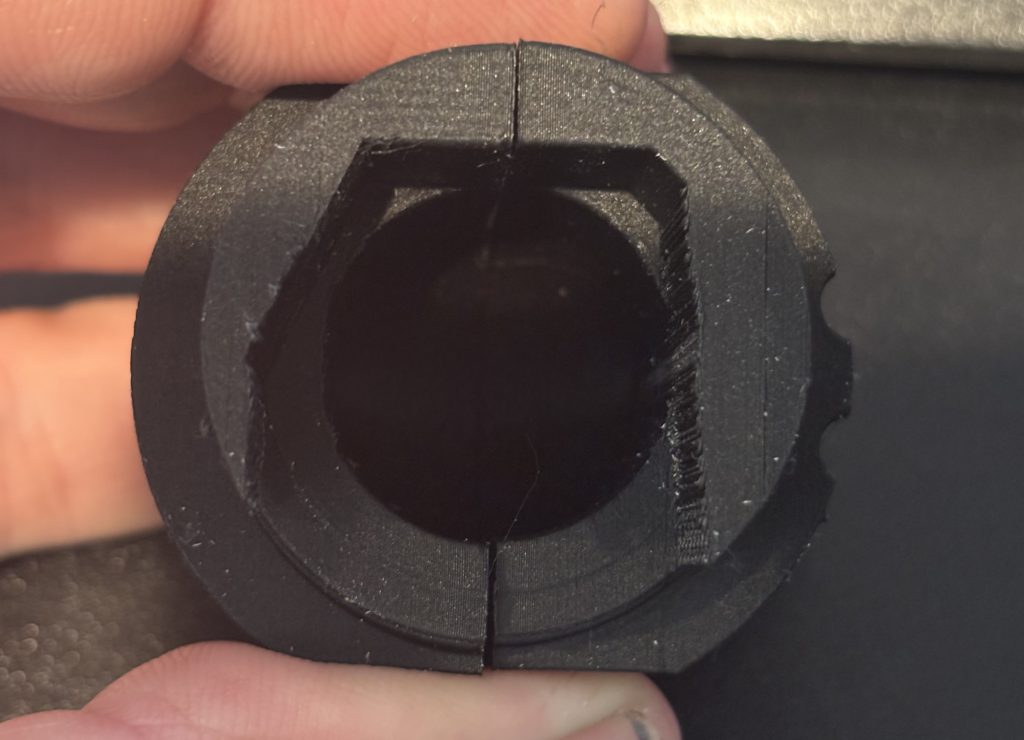
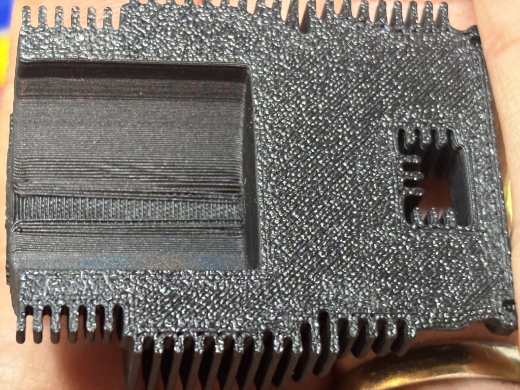
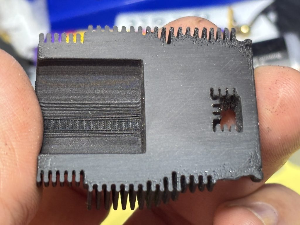
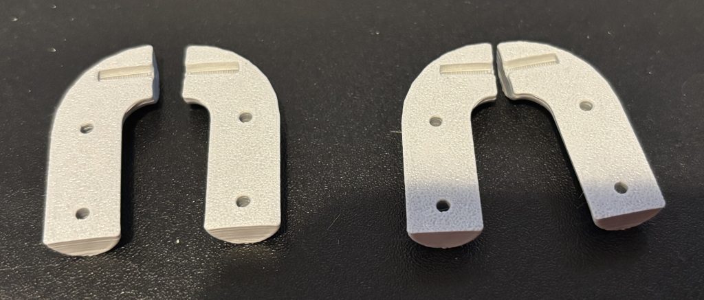
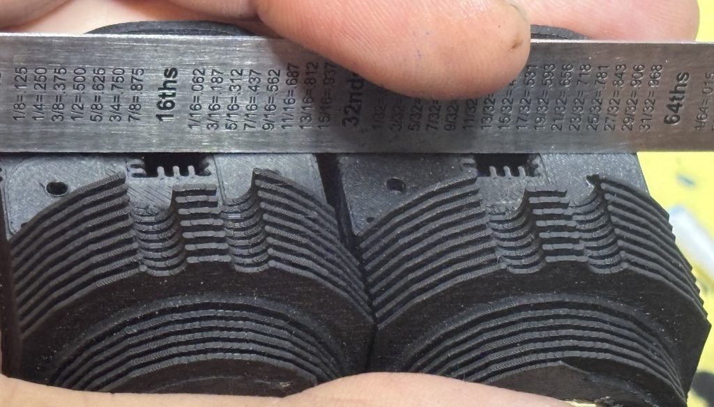
In the kit you will see where all the flat mating surfaces have this crinkled texture on them from the build plate in the printing process. It is recommended on a flat surface to start with 100 grit sandpaper and sand this out. Then follow it with 400 grit sandpaper. Use caution on the cylinders and not apply too much pressure to the fins and break them. You will need to do this to all mating surfaces like the parting line on the cylinders, exhaust pipes, and the bottom side of the valve covers. Below on the left is that part as you receive it and on the right is after it has been sanded. After sanding clean all the dust from parts and out of the fins.
Lets make the mounts
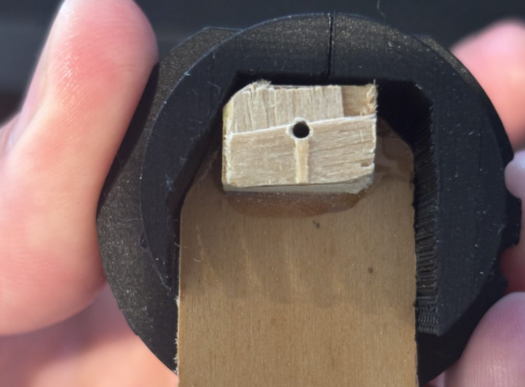
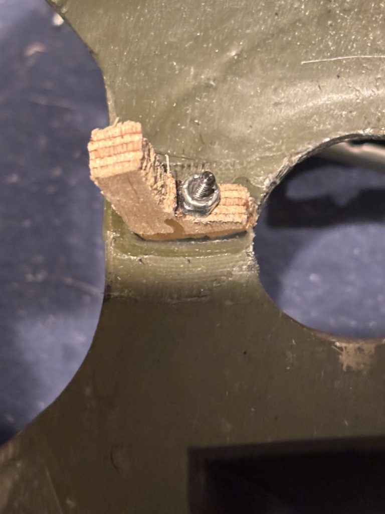
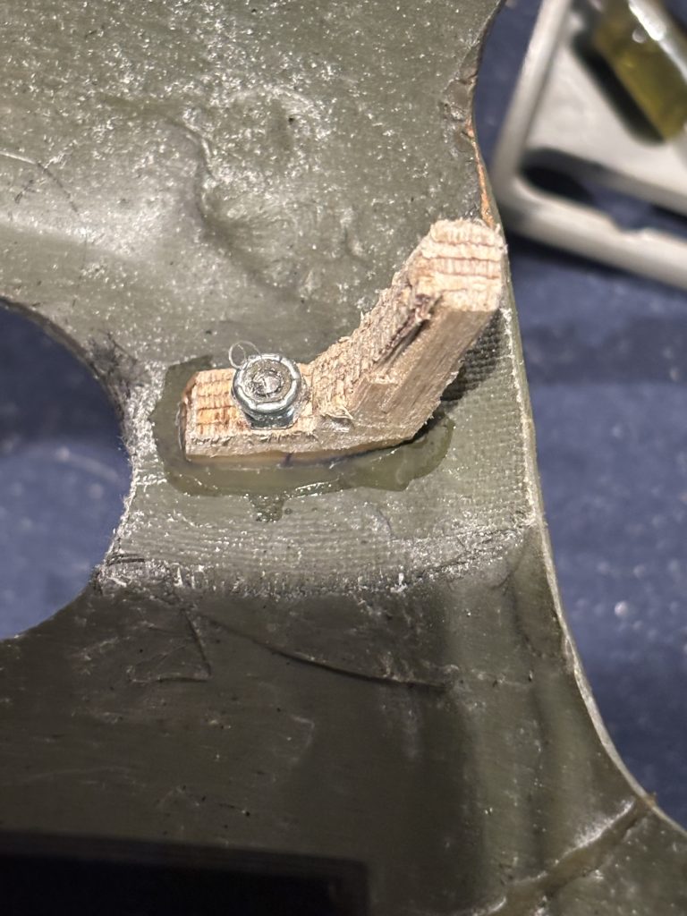
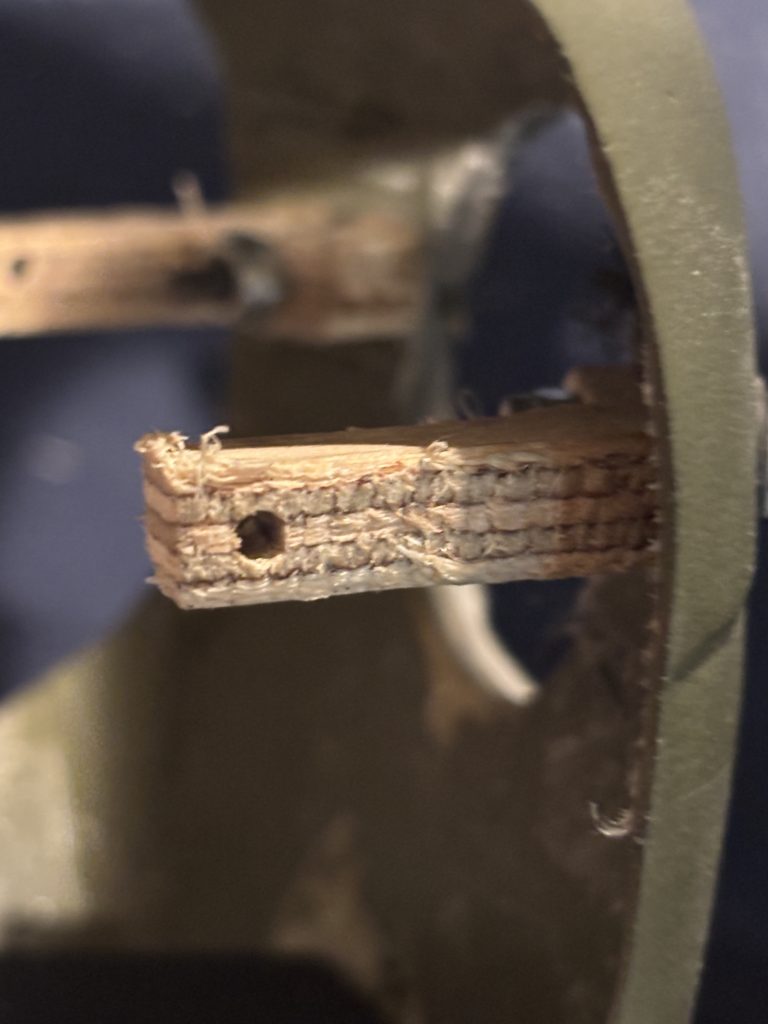
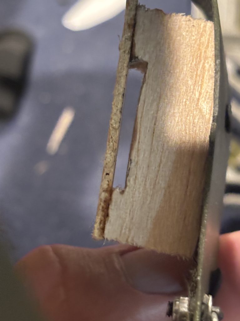
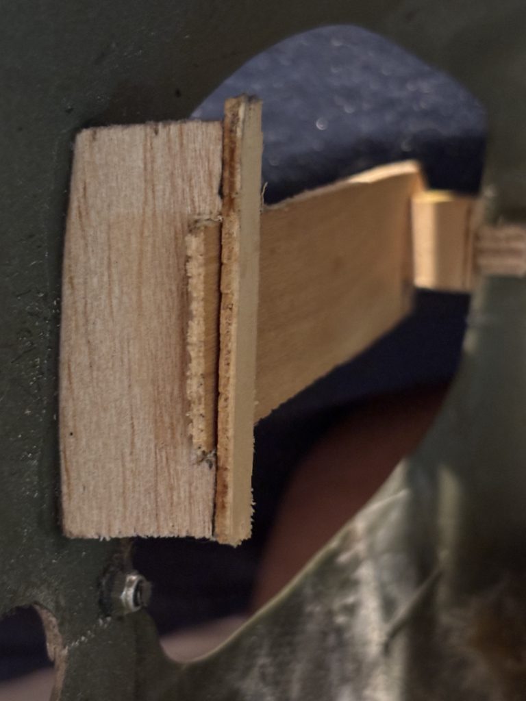
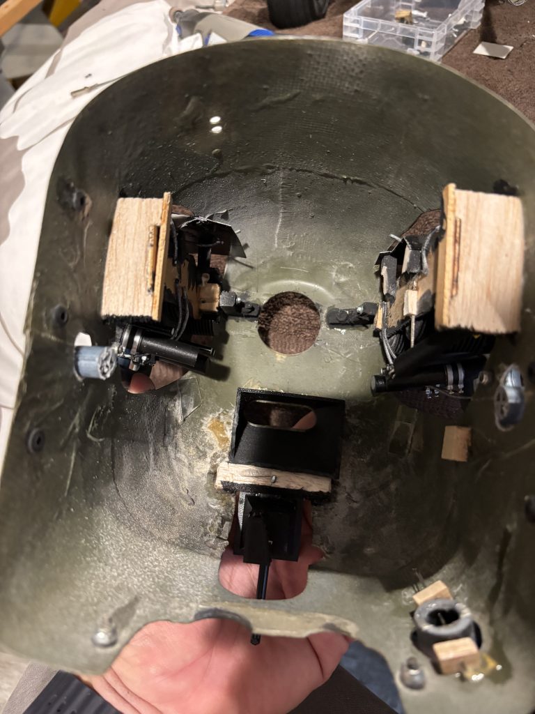
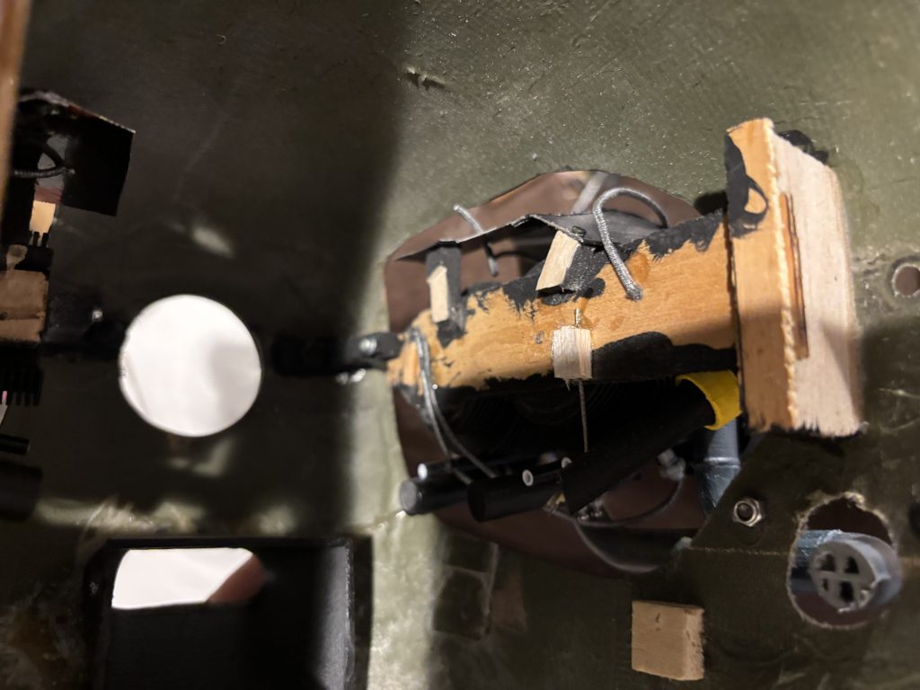
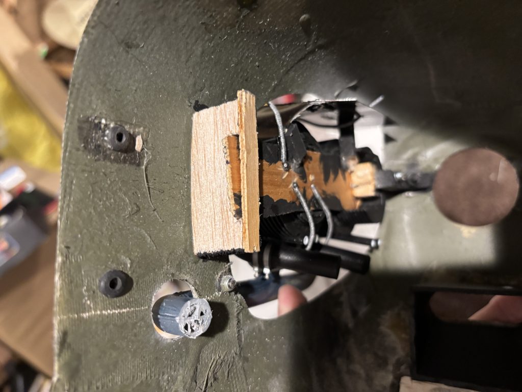
This cowl already has an old set of cylinders mounted and I’m switching out to the new ones, so the cowl openings were already made. With existing openings, you may have to modify them a little to make them work. I had to tilt the center line down just a hair as the old one was not proper lined up. If you have a new cowl, I recommend cutting slots on both sides for where your mounting plates will run. We can open the spots up more after the cylinders are built. Check out my section on Mounting a cowl. For the front two 4-40 Rigging Couplers I extend them through the 1/4 ply front mounts. The next three photos show the front mount made from 1/4 ply. This is something you will need to customize to fit your cowl and set up.
For the rest of the mounting setup, it’s all going to be custom work to fit your cub. If you need help, I’m just an email away.
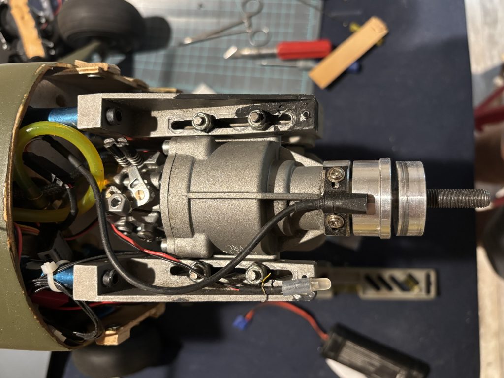
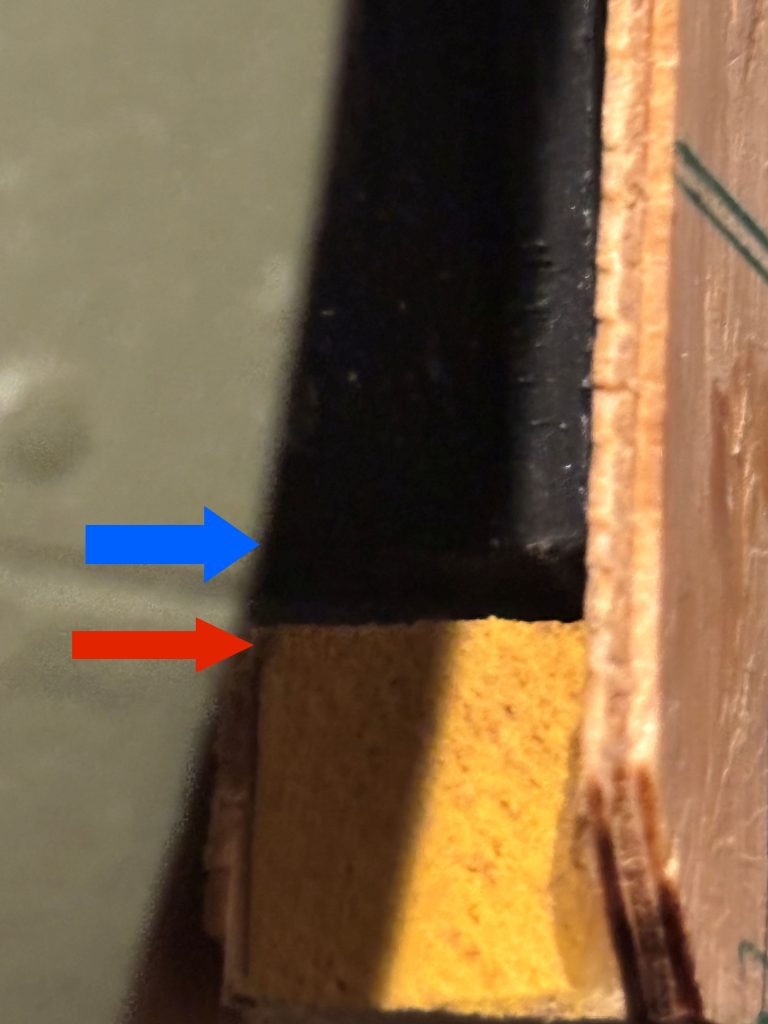
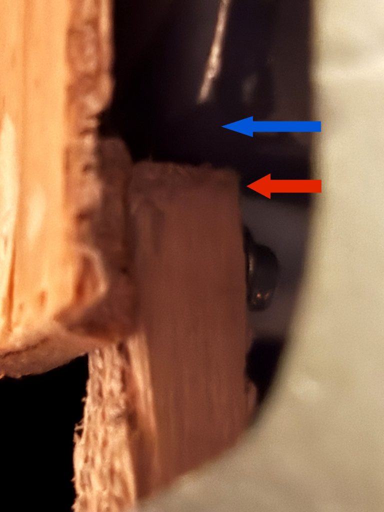
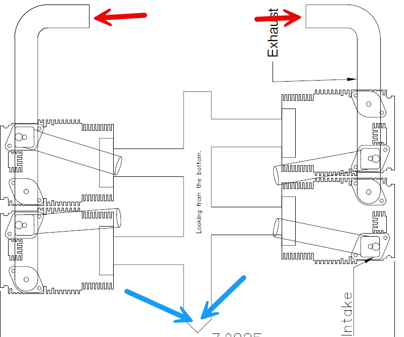
Looking above will give you an idea of my engine mount and what I have to work with. For the side mounts I use 1/16 plywood. This is another area that you will need to customize to your setup. For the 1/4 scale make this part about an inch tall and from the front to the back of the cowl We will trim it when finished. As you see below one side has to be spaced out a little farther to clear the motor mount. The blue arrows show the motor mount and the red is the spacer block I used.
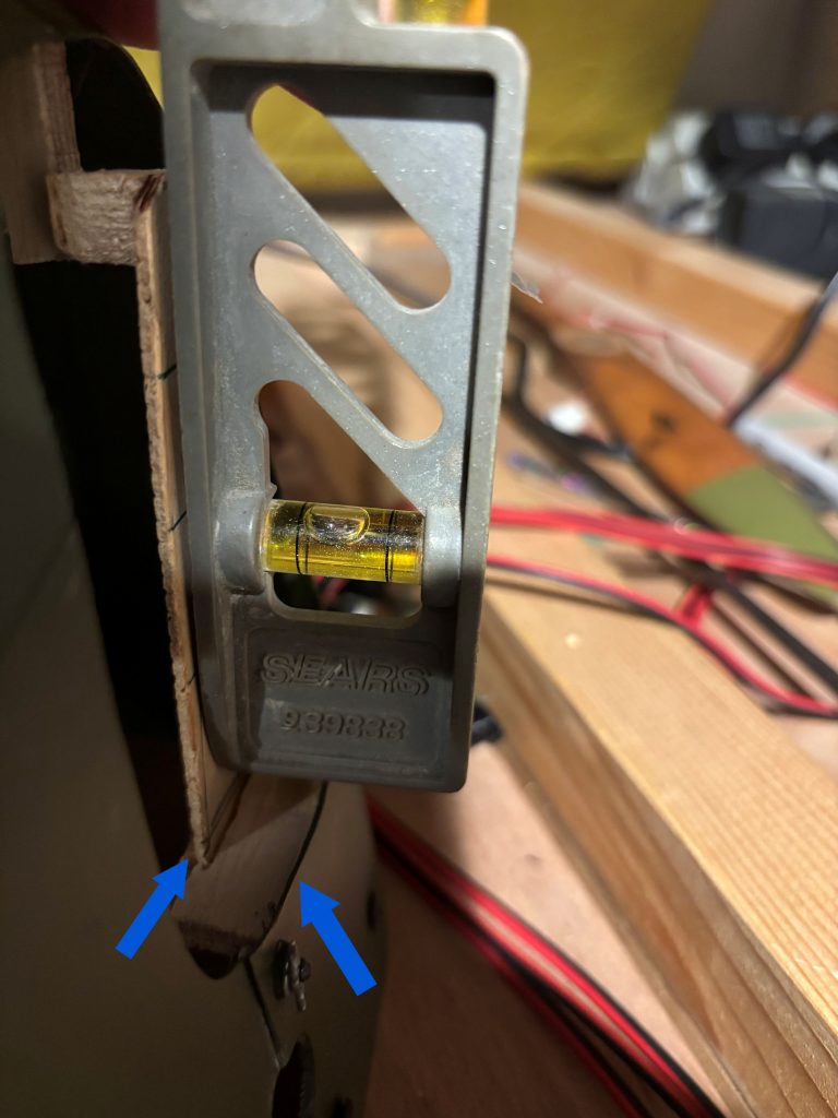
Now that you have that part figured out, lets figure the back mounting blocks. I like to mount the side mounts to the front blocks using servo screws. With your cowl setting on a flat surface, I use a small level and get the side mounts strait up and done and then measure the distance from side of cowl and the 1/16 plywood side mount. that can be seen by the two blue arrows below.
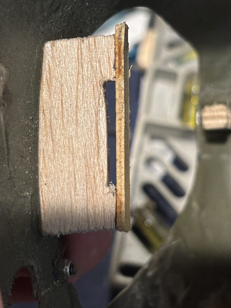
For the back mount I use some hard 3/16 thick hard balsa and a 1/16 ply cap You will need to take measurements from above to make the back mounts. See the photos below to give you an idea of what we are doing. You will need to custom make them to fit inside the cowl. You will cut a small slot out to allow the 1/16 ply site mount to set into the slot. Then glue the 1/16 ply cap onto the block. When happy glue the mounting block into the cowl
This is with the side mount in place and trimmed
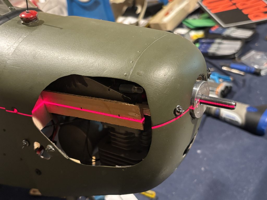
I have a small laser level that shoots a horizontal beam and its mounted on a tripod. I set the plane up on a table and level it both side to side and front to back. Using the center of the prop shaft as a point I shoot a line down both sides and mark the center line on the side mounts.
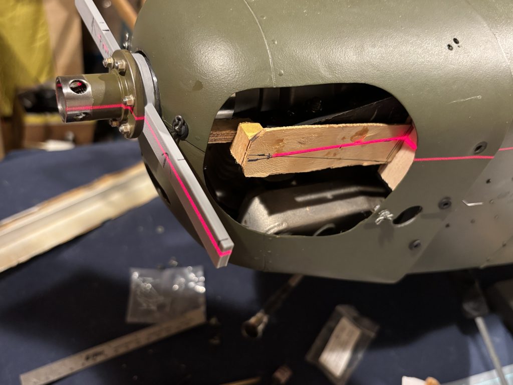
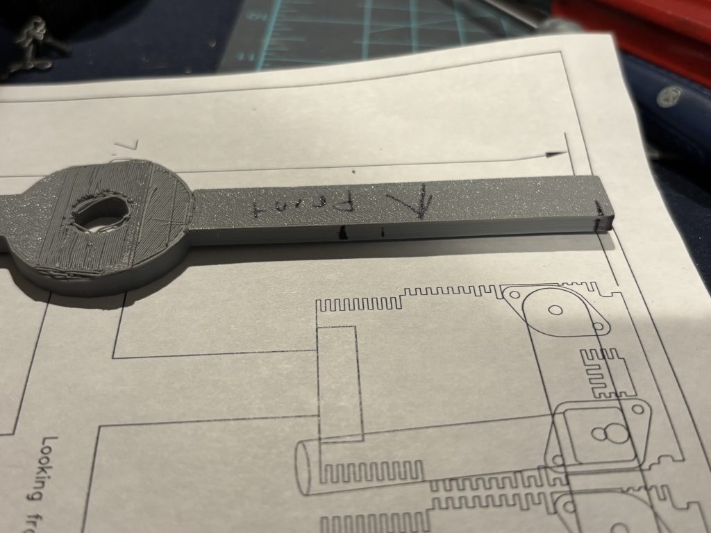
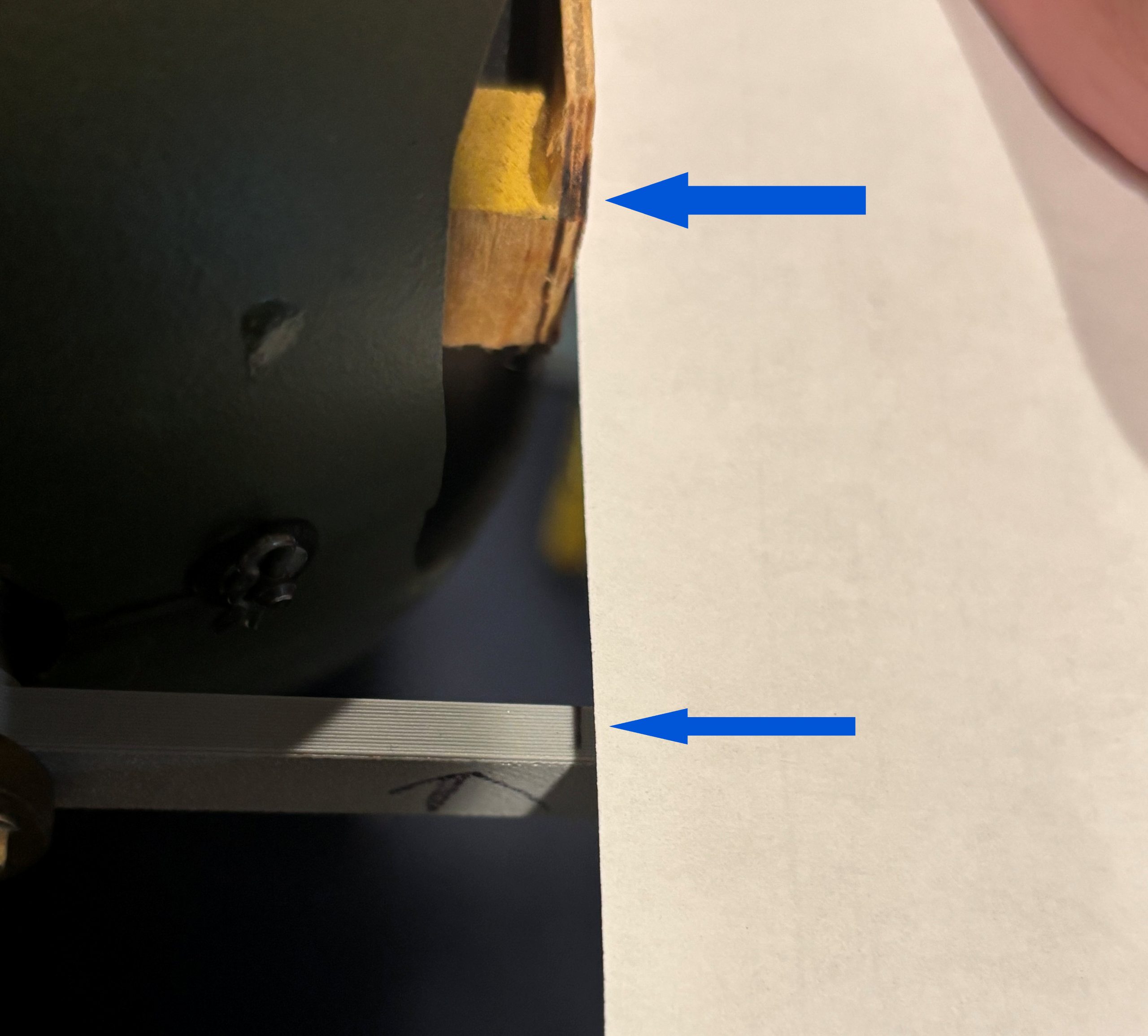
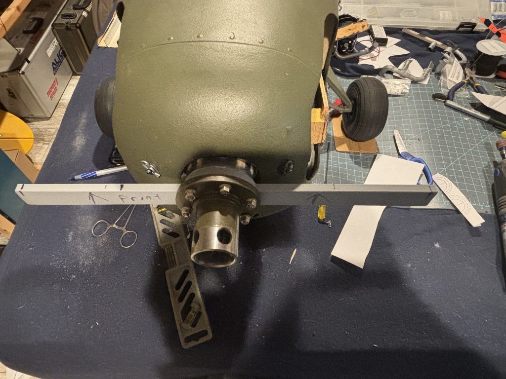
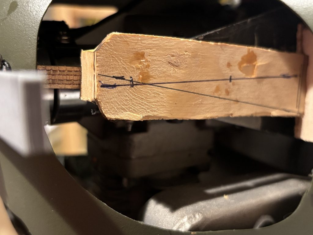
For the next step we need to do some width figuring. Mine was 3D printed but you can make this out of some scrap. You will need a cross bar that is as wide as the engine 7.0885 for the 1/4 scale setup. Mine has a small angle on the center disk that is the 1 deg of right thrust. The cross bar must set flush to the prop hub. With this bar installed with the cowl on, bring a line straight forward from the side mounts and mark it on the cross bar. This can be seen with the blue arrows on the middle photo. Do this for both sides. This will tell you how much for each side the cylinder needs to be trimmed.
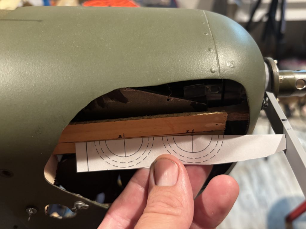
Still with the bar mounted, now let’s mark the center of the cylinders on both sides using the template provided. Flush the front up to the bar and then mark the center points. At this point if you are using an existing cowl with existing holes we need to measure on each side from the bar to back where the center of the exhaust turns into the cowl. On the spacing page (spacing from blue to red arrows) see if it matches up with the exhaust layout. You may need to trim the side pipes when you come to that section on building the exhaust.
Now we have the center marks for the cylinders. I like to round or cut the corners at 45 deg of the side mounts. Now that the side mounts are made, and from above step with the bar you know how much you will need to trim from the side of the cylinders I recommend laying the side mounts on top of the template and sketch them out to give you an idea of what to trim and shape. You can see that below. Any and all trimming of the printed parts I recommend doing in a well-ventilated space due to possible fumes from cutting.
Cylinder Assembly
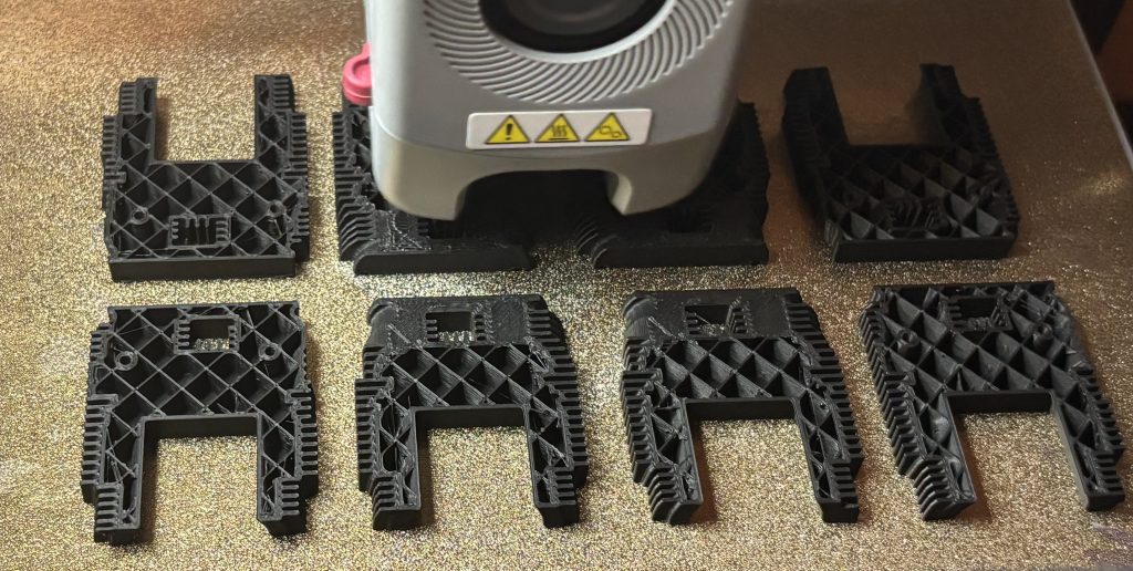
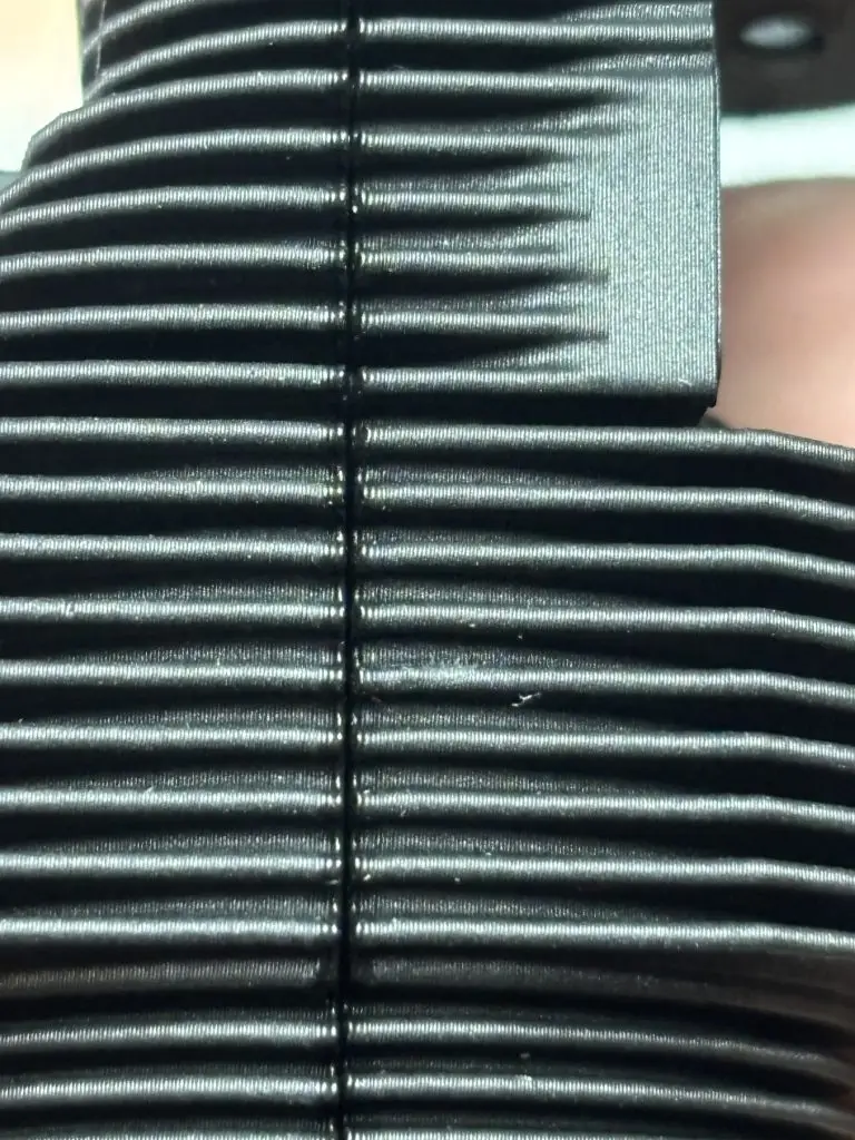
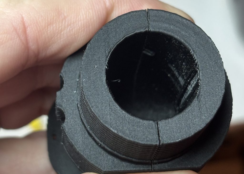
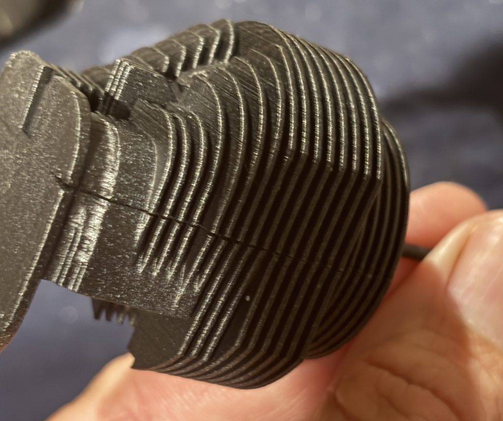
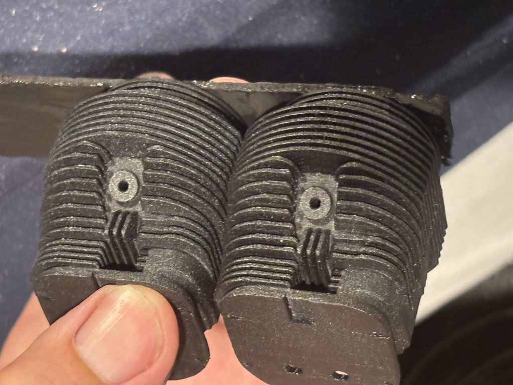
The cylinders are printed in two sections. This split line is where on the full scale you can see a casting mold split line. By splitting them, it aids in an easy part to print, along with more accurate details. Fill free to put the two parts together and roll but you will have some gaps where the fins meet on the split line. This is due to the texter from the print bed. Will not affect the parts in any way other than being able to see the visible cracks. But as we talked about above, it is recommended to sand this down for a better look and fit. Remember to use compressed air or a stiff bristle paintbrush to clean all the areas of dust.
Keep checking for the gap to close up on the parts. When happy with the looks, glue them together with med CA and set aside to dry. That parts do not have any alignment pins so you will need to work fast and check that the fins line up on both sides before they dry. I like to also apply some then CA to the seam from the inside and allow it to wick into the crack.
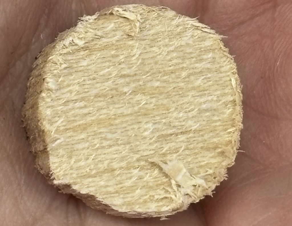
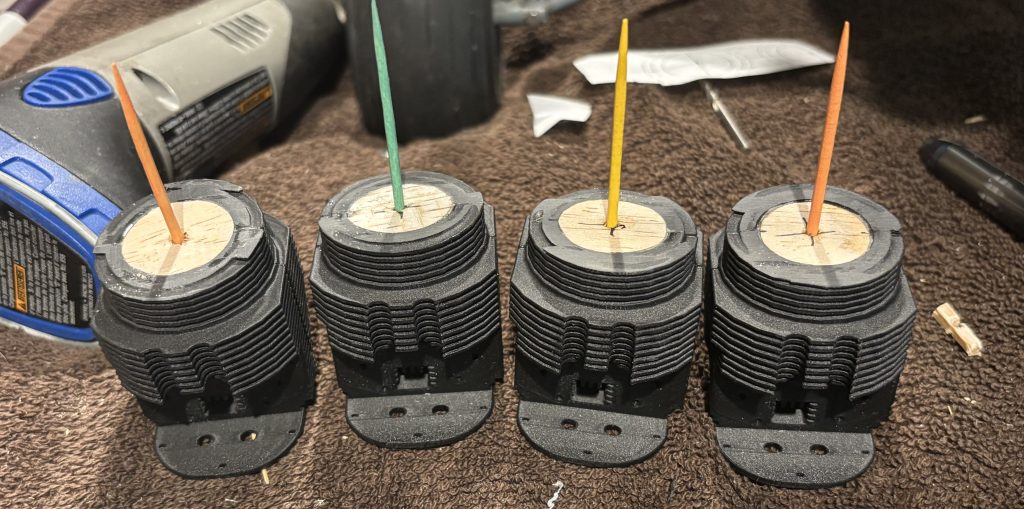
I like to take 1/4 to 3/8 balsa and cut small disk to be inserted inside the cylinder. This is a rough cut one that needs to be sanded down for a snug fit. Drill the center and CA a toothpick in it. Chuck it up in your drill and spin it while you sand it down for a good fit. When happy with the fit use med CA and glue into the cylinder. It needs to be glued in flush with the bottom of the cylinder. I also like to run a small line of thin CA and let it wick between the wood and plastic.
The toothpick installed above will give you something to hold on to while you spray paint and will be used to attach each cylinder to the mounting block. Give them a good blast of air to remove all dust before painting.
NOTE:
Due to the way the cylinders below will be mounted in the plan the bottom is at an angle and will not be flat. Your setup may be different.
Let’s work on the exhaust setup.
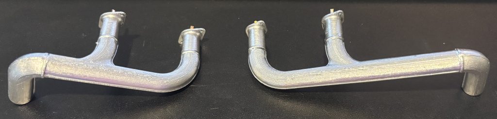
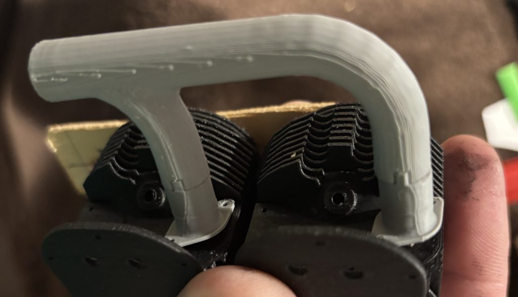
You will have two sets of tail pipes, two sets of side pipes and 4 drop downs.
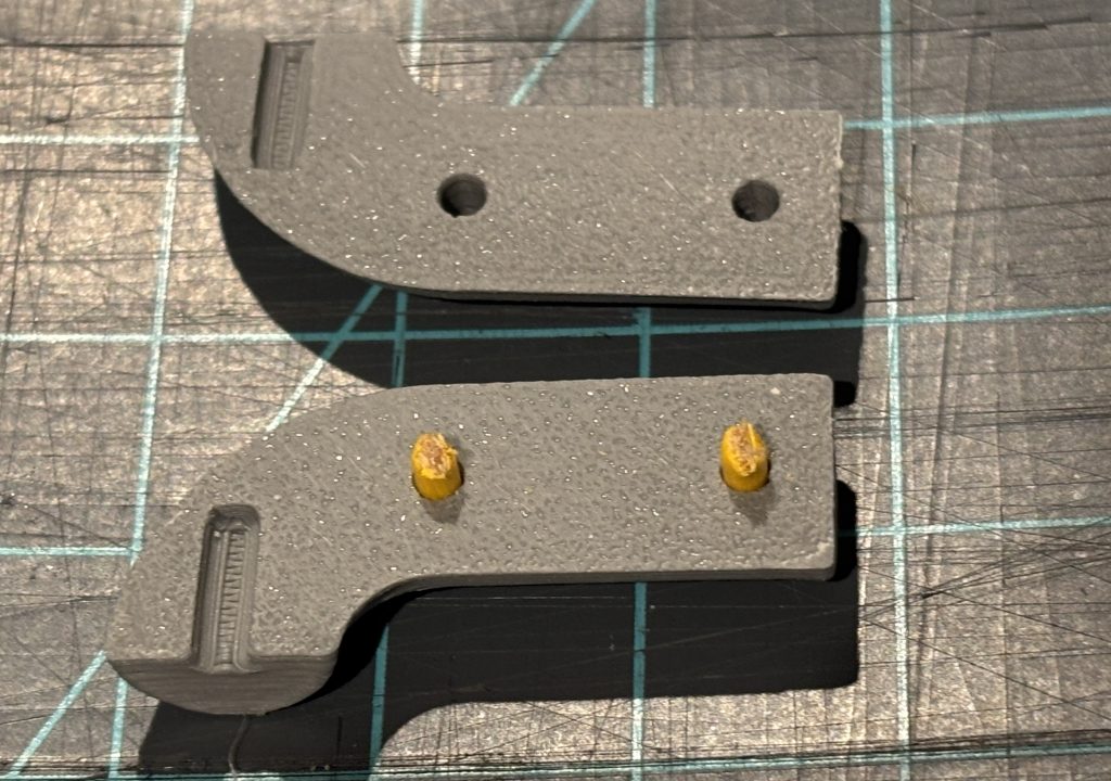
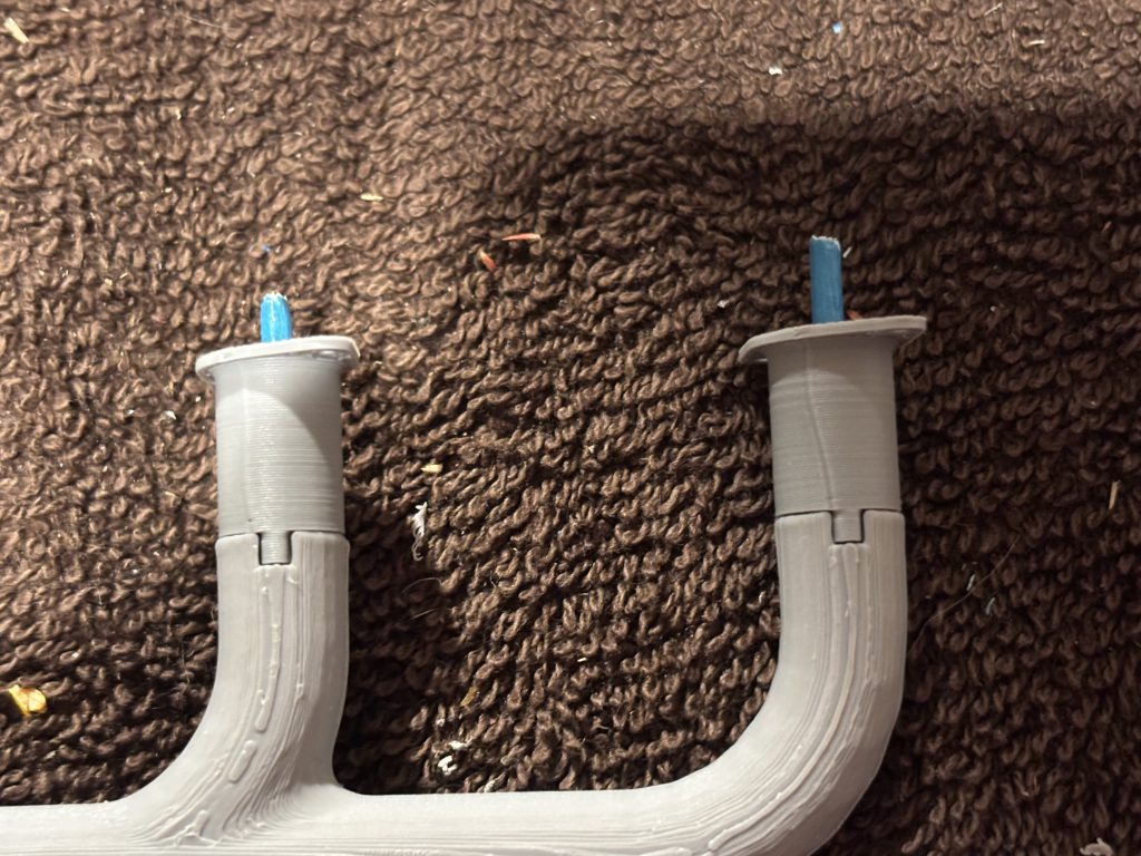
For the side and tail pips you will need to sand the matting sides flush. As said at the beginning it is recommended sanding the mating surfaces to remove the texture surface and make a clean joint. We use toothpicks as mating pins in this build. When you have the surfaces, all flush cut a small section of toothpick and insert in the holes as seen below. You might need to drill (3/32 bit) the holes out a little for your size of toothpicks. I like to do a test fit before applying any glue to see if the toothpicks need to be trimmed any. When happy use med CA and glue the sides together.
Do this for both sets of side and end pipe.
Now is the time to trim the length of the side pipe if needed in the above step of Lets make the mounts you were to measure and see if the side pipes need to be shortened.
For the down pipes they are keyed to only go one way onto the side pipes. Test your fit first then glue when happy. I take a full length of toothpick coming out of the side pipe and drop the down pipe down into place. Again, the holes in the down pipes may need to be drilled (3/32 bit).
I did not get a photo of before I trimmed the toothpicks but again the help to hold the part as you paint it.
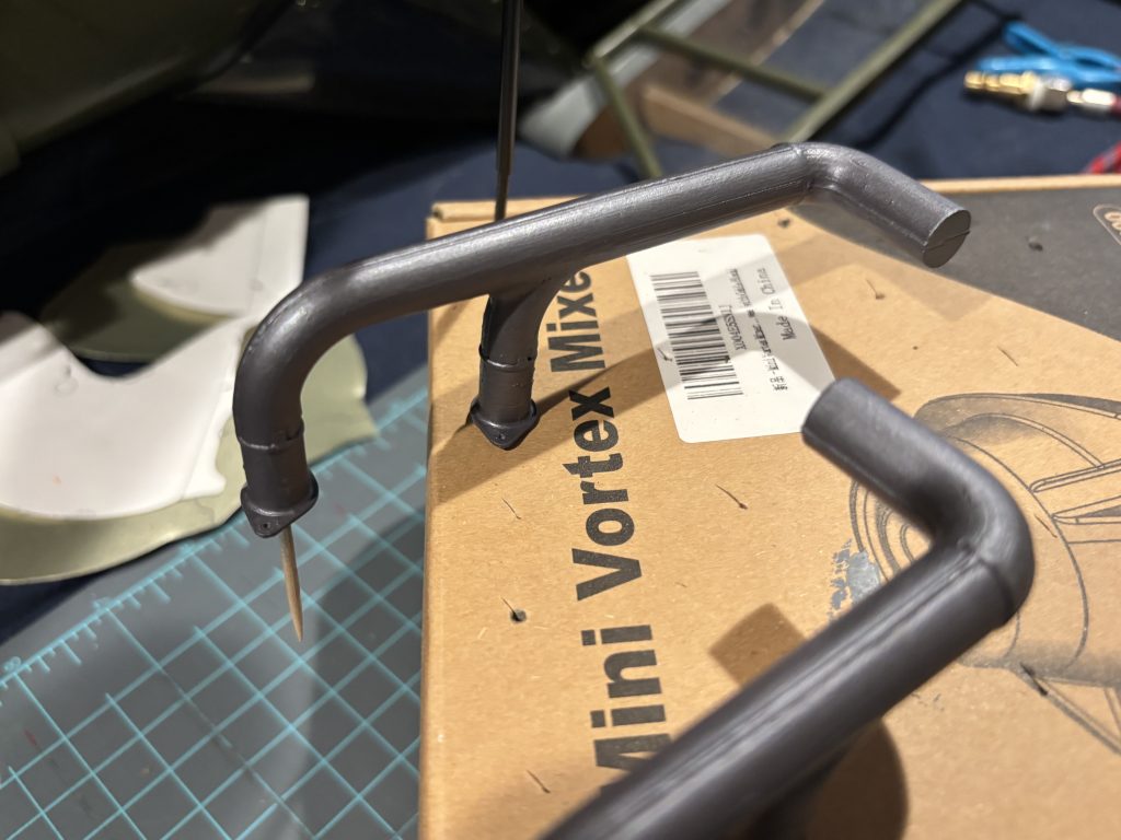
With a toothpick cut to length lets attached the tail pipes. They will be at a 90 deg to the side pipe See photos of how they should look.
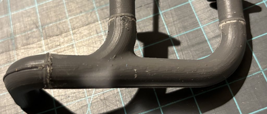
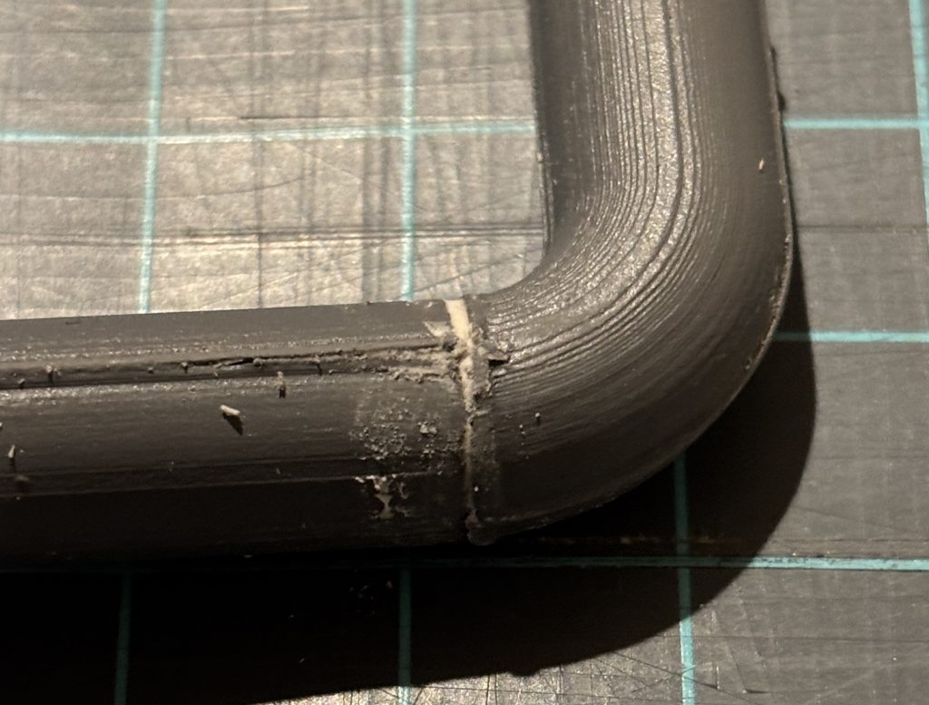
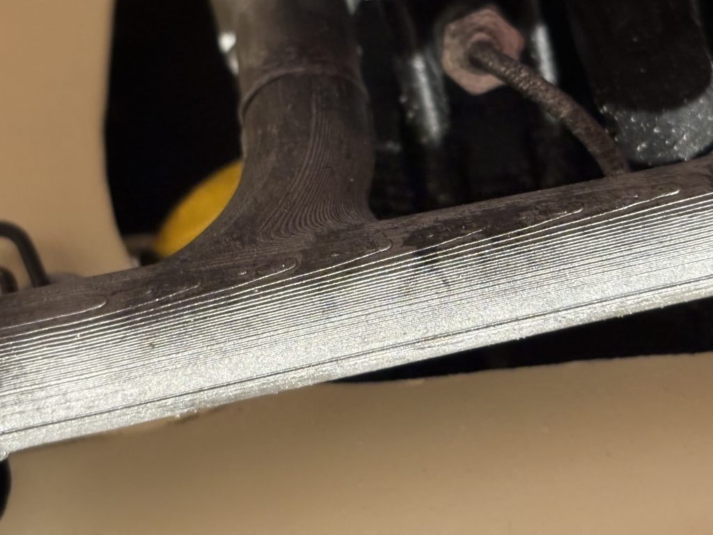
After the glue has dried, I like to use good old Testors Contour Putty and fill any small cracks from mating parts. Let this dry and then do any sanding that is needed. A few coats of spray primer and then light sanding will help with the layer lines. Use caution and do not sand out the simulated weld beads on the parts.
Paint the Exhaust
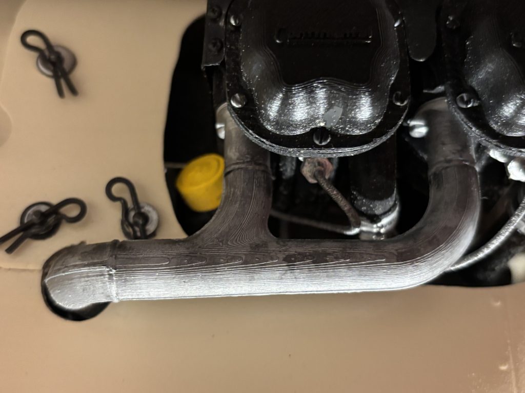
Now how scale do you want? You can spray it with the aluminum ( As seen below) and be done, or we can take it to the next level.
For my cream cub, it has what I call a dirty silver exhaust. I sprayed a good coverage of aluminum and let dry. Then I came in with Oily steel and Black Gray and made it dirty looking. I used like a dry brushing technique of the colors and then my finger to smear it in good. Let it dry and then spray a couple coats of clear mat to dull it down.
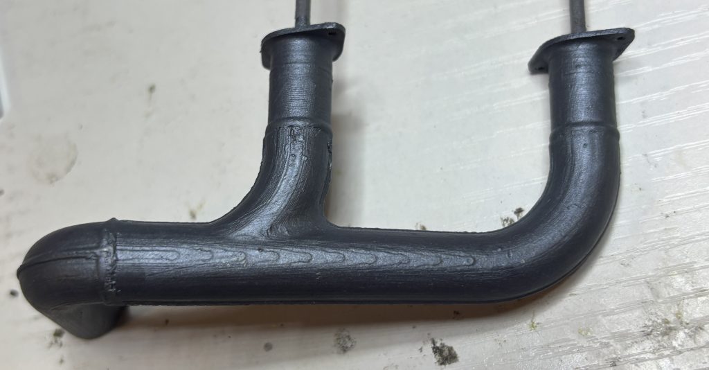
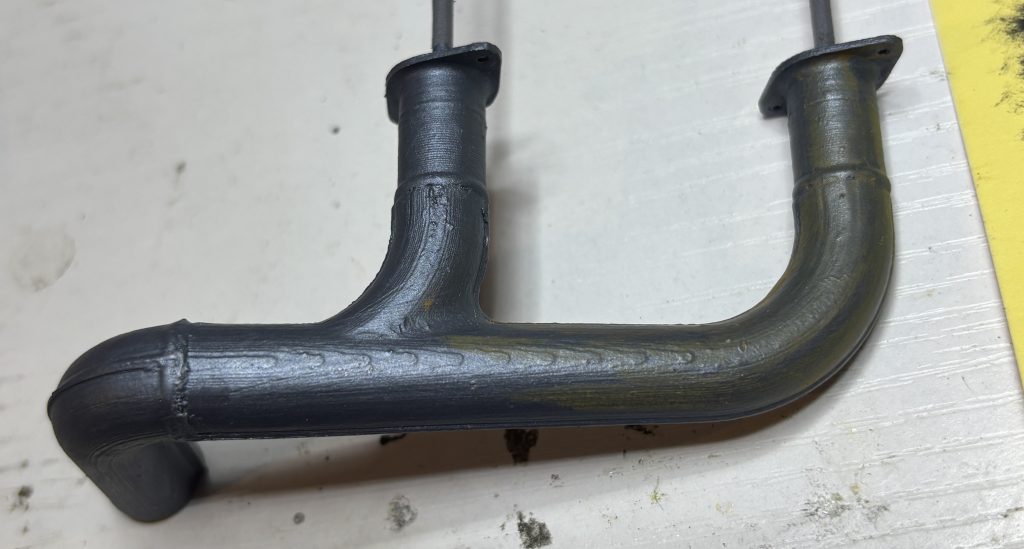
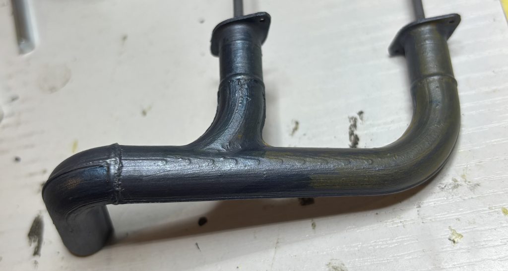
For my L4 it’s different, it has a darker gray look with some blue and orange hues from heat. I used gray spray primer for the base. Followed that with a mixture that had 2 drops of Magic Blue, 2 drops of Bloody Red and 18 droops of Oily Steel.
Next for the front section there is an orange tent on it. I came in with Yellowish Rust, and I used a dry brushing technique of the colors and then my finger to smear it in good.
Next for the back section there is a blue tent on it. I came in with Gunmetal Blue, and I used a dry brushing technique of the colors and then my finger to smear it in good. After it dried, I hit it with a coat of mat clear to dull it down a little.
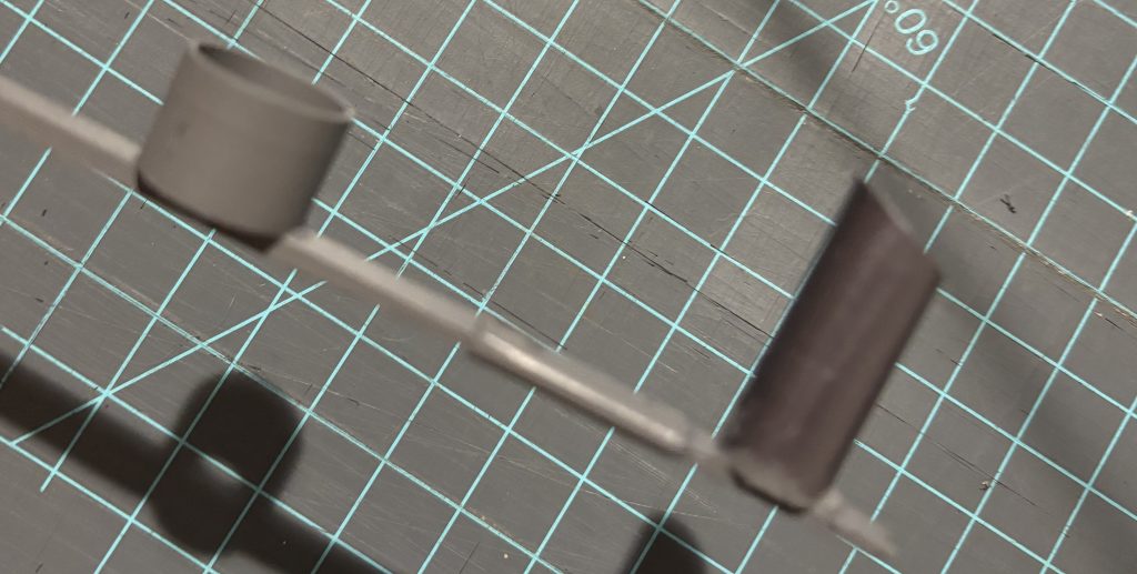
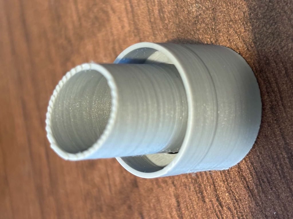
The tail pipe is composed of two parts. Paint it to match your exhaust from above. I like to use the Black Gray to paint the inside of the tube to look like a burnt exhaust. When finished glue the inside tube to the outside and this will finish this section.
Intake manifolds
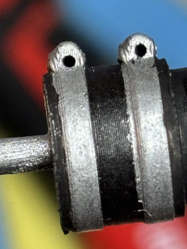
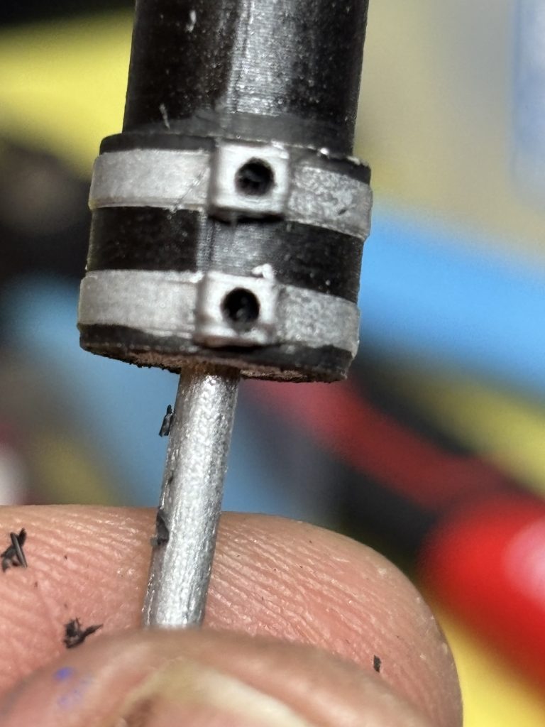
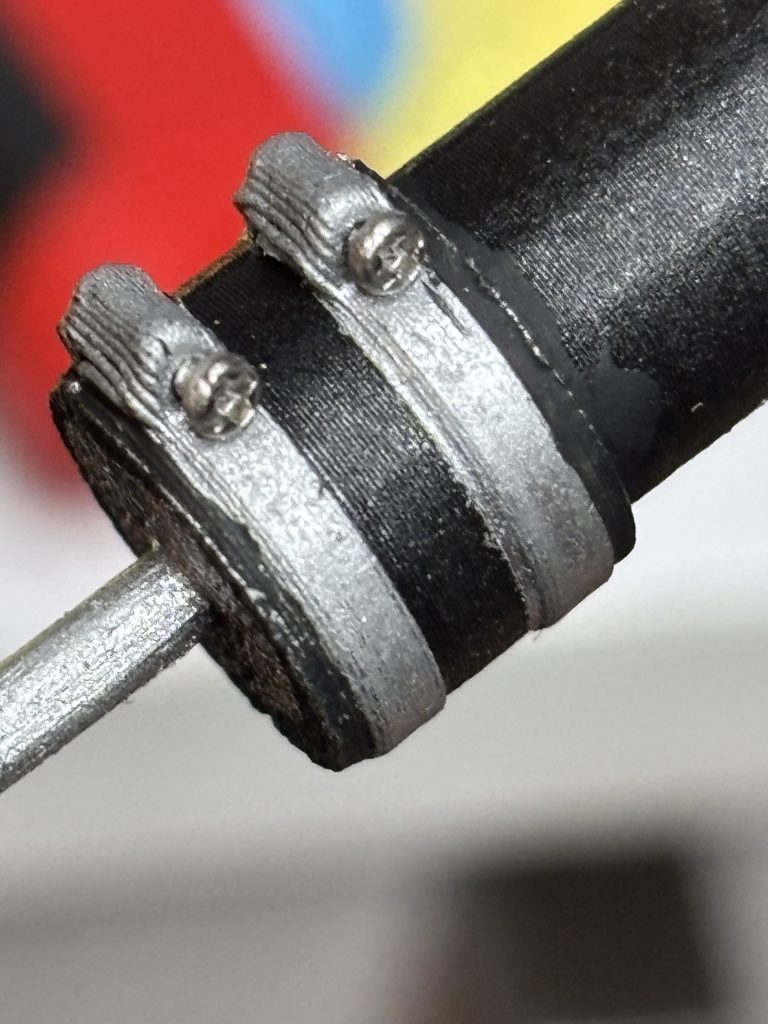
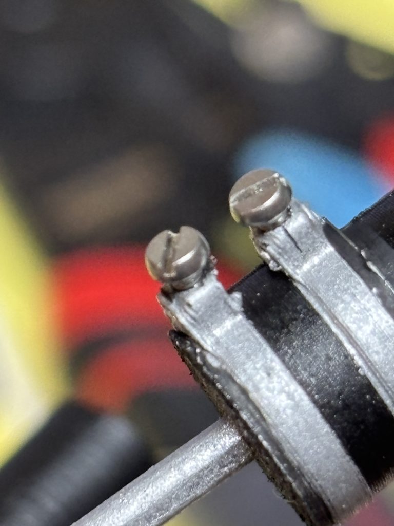
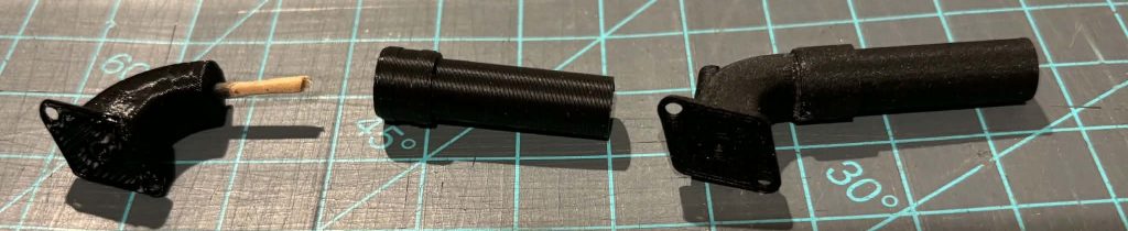
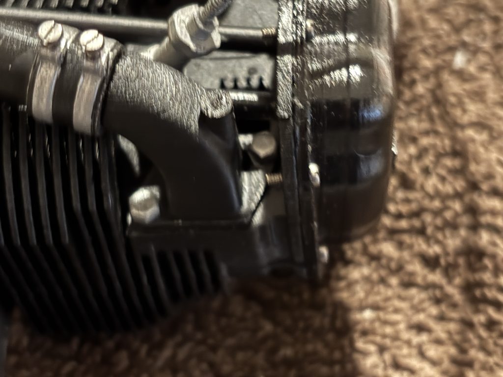
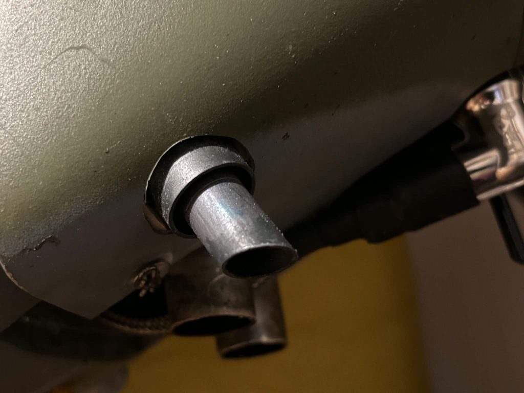
The intake manifolds are made up of two parts. The elbow and the straight tube. On the full-scale this two parts are connected by a small section of rubber hose using two clamps on it to secure the hose. I sprayed the parts with the proper sheen paint. For me it was mat black. Let this dry overnight. Next, we mask off the area of the clamps and hit it with a coat of aluminum spray paint and let dry. You will see they used two clamp styles. One with the screw parallel with the clamp strap and one perpendicular to the clamp strap. Now with a 1/32 bit drill the proper holes as shown below. Take the screw and carefully screw it into the clamp.
As with so many other parts of this build, we use a section of toothpicks to join them. You want the clamp section to face toward the bottom when glued together you may need to drill the holes out with a 3/32 bit.
Photo below is of the to sections and then glued together The photo was taken before the clamps were added to the print.
Sparkplugs and wires.
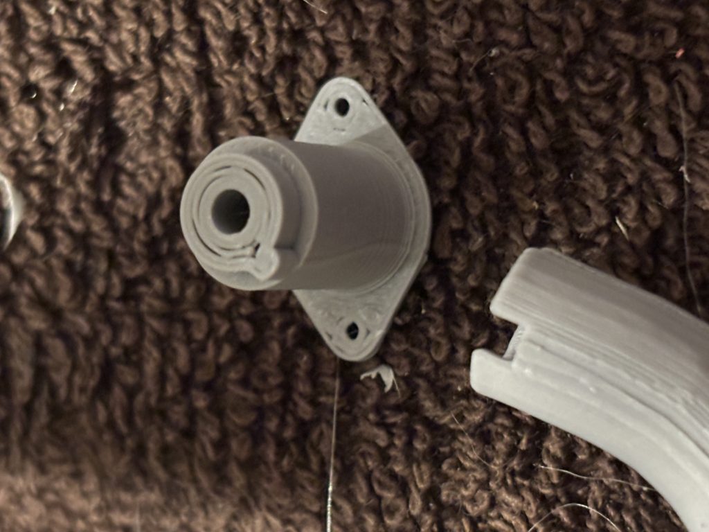
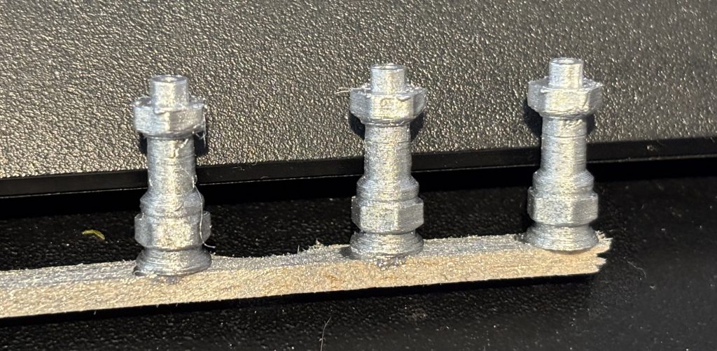
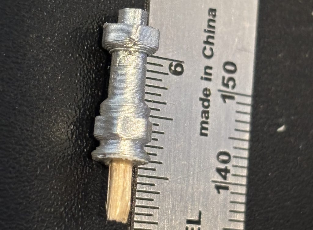
Hit the plugs with a good coat of aluminum spray paint. Let dry then a coat of mat clear and let dry. With a3/32 bit drill the bottom holes to accept a toothpick. The bottom has the flange as seen below. For the top hole very carefully drill a 1/32 hole for the plug wires.
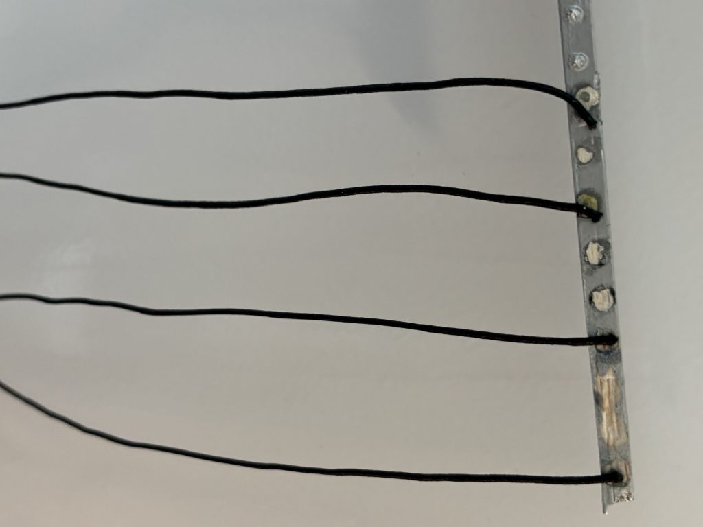
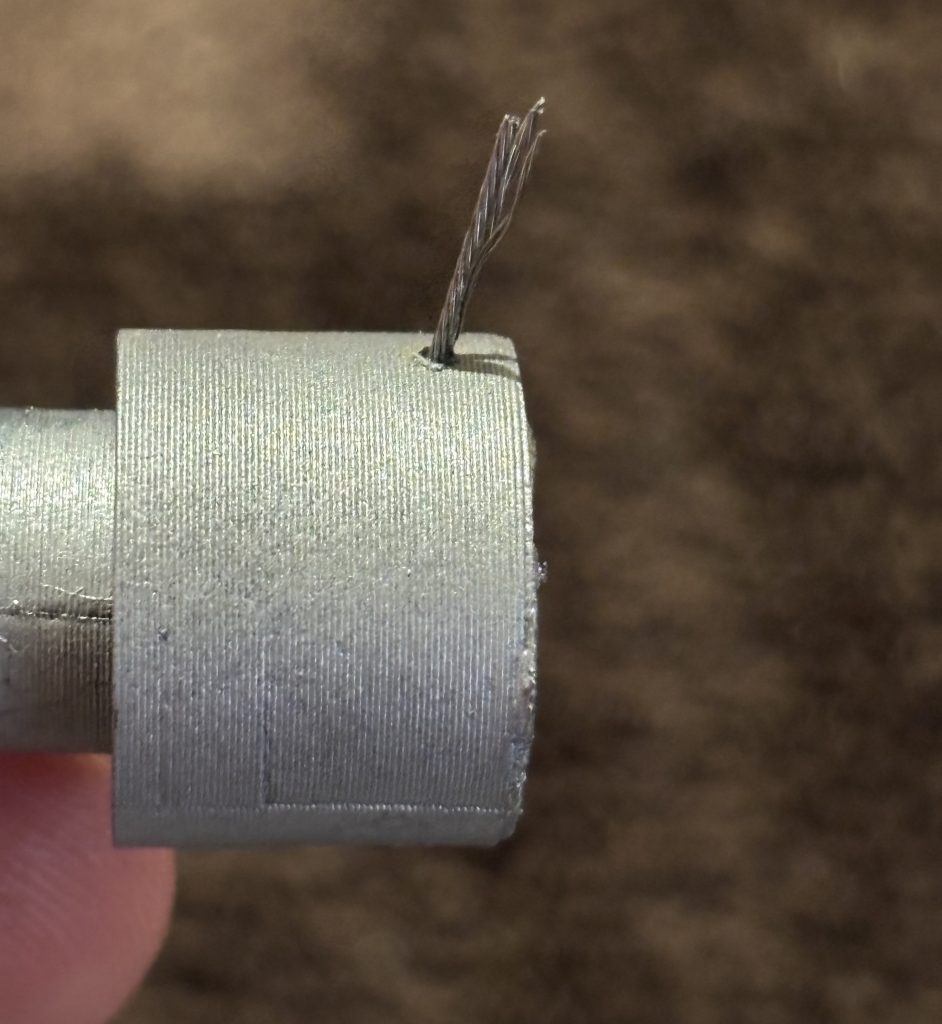
.Now take the black elastic cord. On some planes the plug wires are black, on some are silver. For mine they are silver. I spray them with a good coat of aluminum spray paint and let them dry. Cut the wires to a 3.5 inch lengths. If you place a drop of then CA on the wire before you cut it it helps to hold the shape. Now glue the plug wire into the top of the plug.
This will finish this section.
Assembly time
Time to put it all together. We will need to sand and prep the back side of the valve covers. Sand as described in the top section to remove the roughness from the back side.
We will need to drill and clan all the holes. On the cylinders you will need a 1/8 bit to clean the holes for the pushrod sleeves. For the plug holes on both side and the center holes for the exhaust and intake you will need to use a 3/32 bit. For the intake and exhaust parts the bolt holes should be 3/32 bit. When drilling the holes on the intake manifold and the exhaust header use a 3/32 bit but be very careful as the thickness of the material is very thin. Let the bit do the work with little force. For where the valve cover attaches drill all the holes with a 1/32 bit. On the valve covers use a 1/16 bit for the holes. Use a knife and clean the edges of any holes that are rough. Blow all parts down to remove any dust.
For my setup, I used mat black spray paint for the cylinders. Semi-gloss black for the valve covers and pushrod sleeves.
Some kits, the 16 hex bolts, are nylon and will need to be sprayed with aluminum paint.
It is highly recommended to use a magnet parts tray any time you are working with the small screws. You will drop a screw or two and this helps to catch them.
If you want to go an extra step in scale, mix up some white with a hint of light gray in an airbrush and just very lightly mist the cylinders. This will give them a hint of heat. If it’s a new engine it will have more of a black look, but a used one will have a hint of areas the paint has been effect by the heat. It’s hard for my camera to pick it up. Just enough to knock the sharp black color
Now take the mounting plates you made up in the mounting section and drill a 3/32 holes for the center of the cylinders. I like to work the front one first and then the back one. We are going to place both cylinders in the holes, use a straight edge and check alignment by placing the straight edge where the intake and exhaust mount to see if they are straight. Should be no gaps visible. When happy, we will apply med CA glue ONLY to the front one and glue it to the mount. We will go through this step again to check they are aligned properly. Let this dry.
Now let’s dry fit the back one. Using the method above for alignment we will also use the exhaust to check the spacing between the cylinders. The toothpicks form the exhaust should just drop in the holes on the cylinder. When happy apply med CA and repeat above step and hold till it dries..
You should now have something like this. Repeat for the other side.
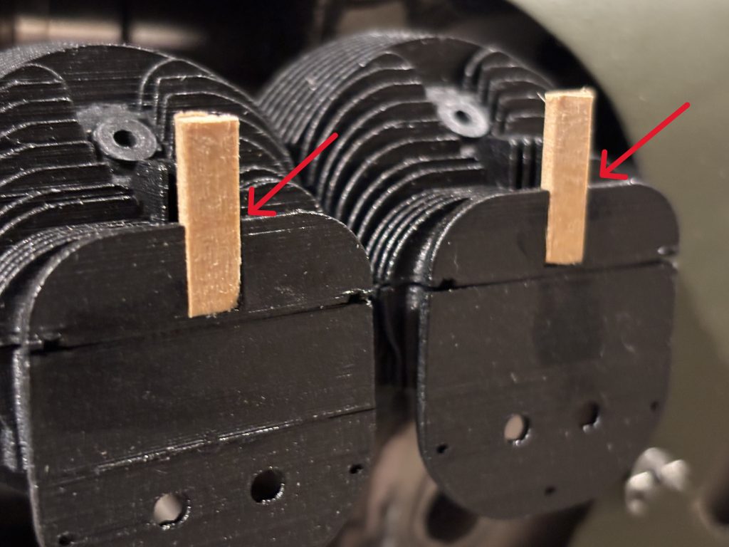
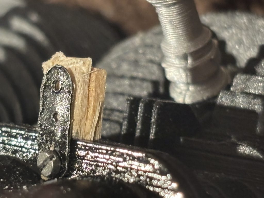
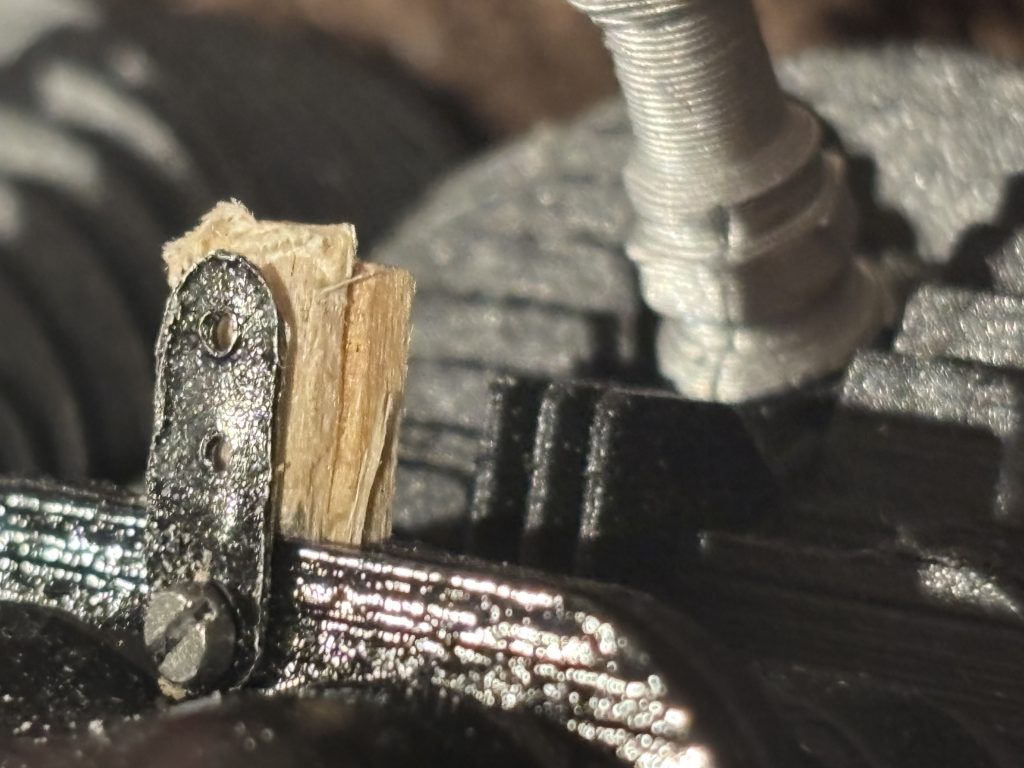
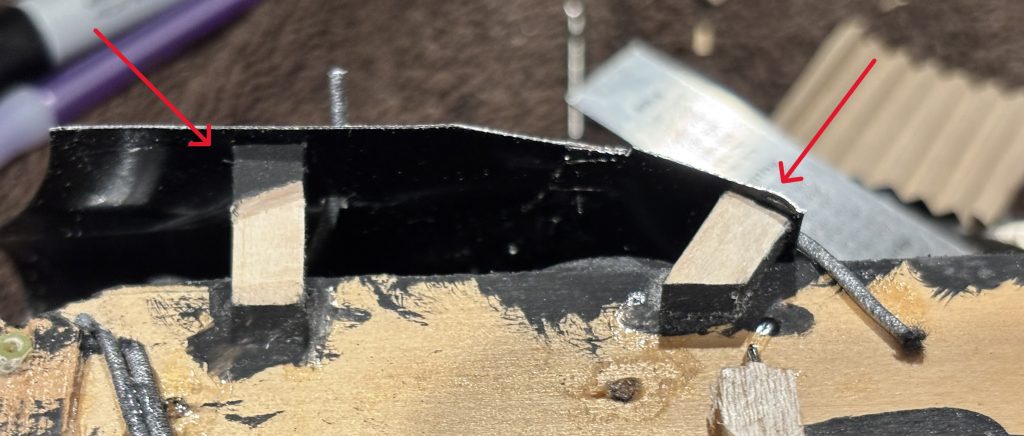
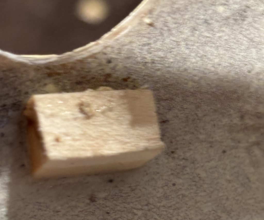
Looking at the surface where the valve covers will mount you will see a notch at the top of each. Cut 4 strips of 1/16 x 3/16 x 3/4. spruce and glue into the slots as seen in the photo. Now take 1/32 x 3/16 x 3/8 spruce. This will be glued to the tabs but just above where the valve cover will be attached. See the red hours in the photo
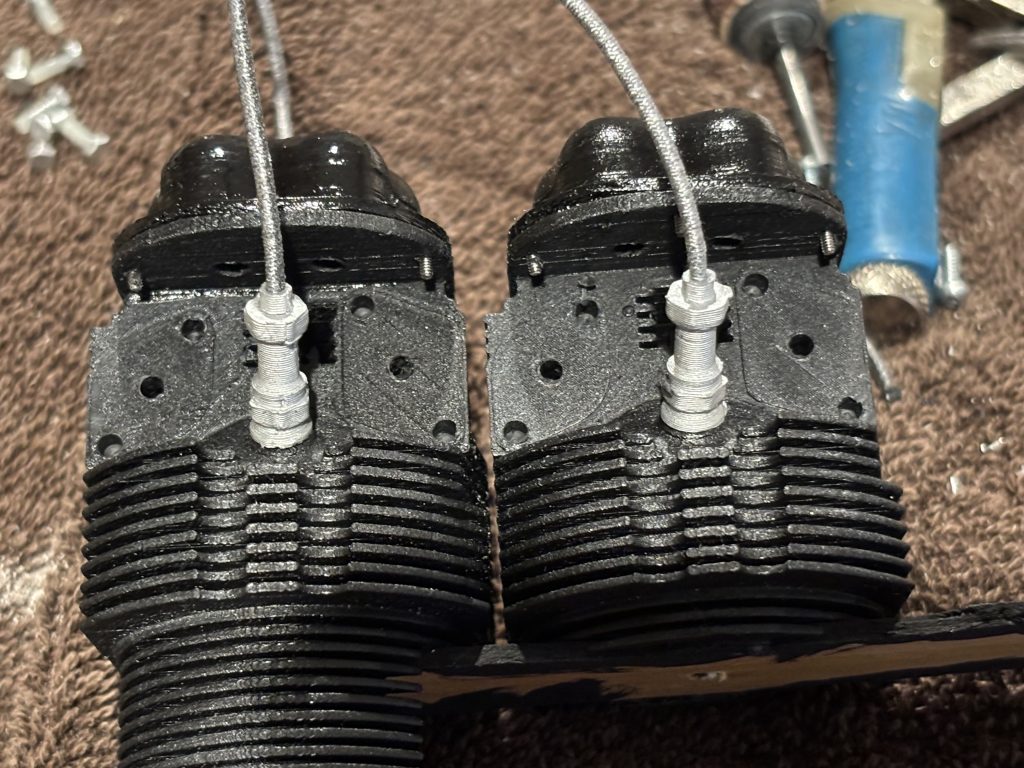
Now using the toothpick. Setup lets glue all the plugs in
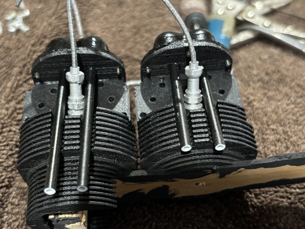
Install the pushrod tubes. I like to cut them to match the length of the cylinders. You can see below how they match up.
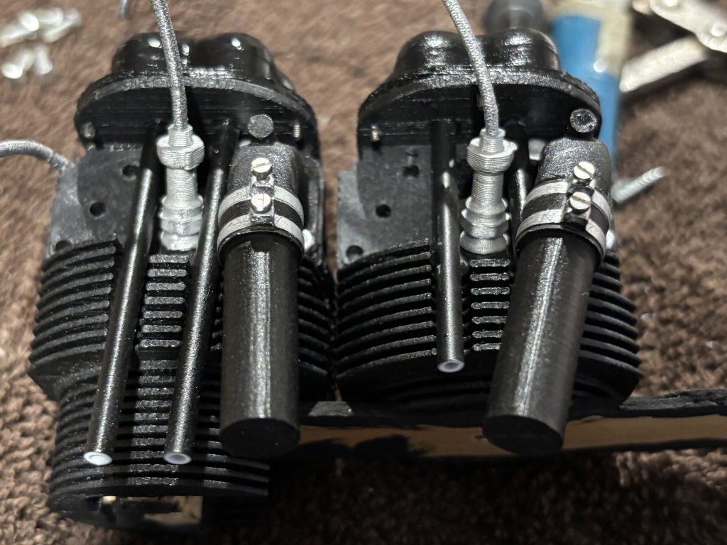
Now using the toothpicks lets glue the manifolds on. Please refer to the spacing sheet for location of where to glue them and in what order.
If you look at the bottom matting surface with the cylinders you will see numbers. When you install the manifolds, you must line the bolt holes up before they dry in place.
Now take the exhaust and check that you have the correct one. Trim the toothpicks and do a dry fit to the cylinders. After a good fit glue, them with med CA to the cylinders.
Now with hemostats, take a hex head bolts and dry fit it into the bolt holes for the manifolds and exhaust. You may need to trim the length a little. When happy use med CA and glue the bolts in. You have 16 of them to install.
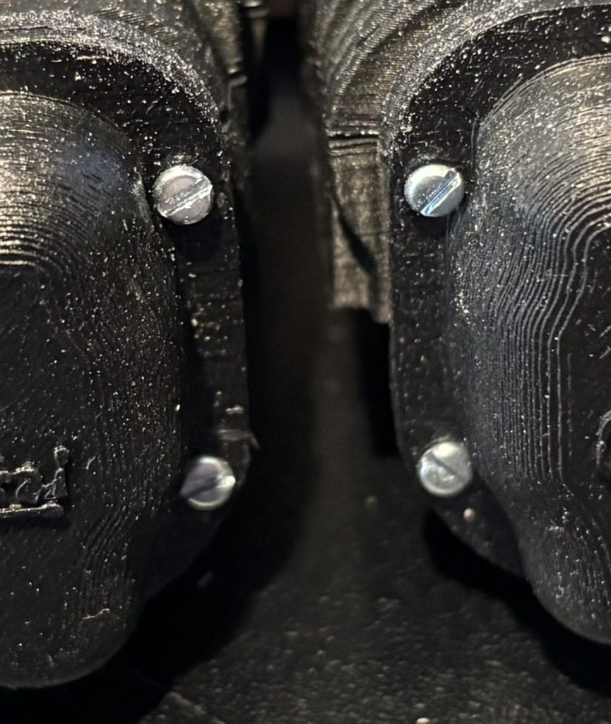
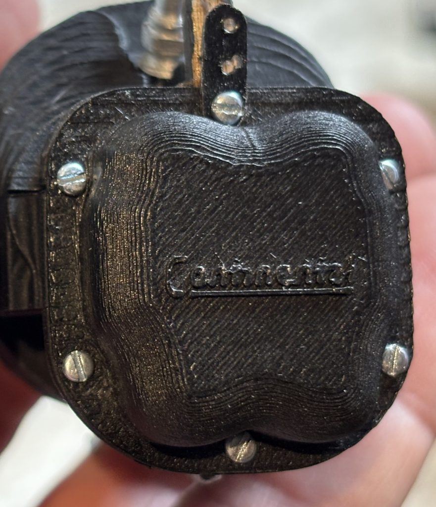
I can no longer get straight head scores that are tapered point. You will need to use caution and little force to get the screws to bite into the plastic. Place the valve cover on and attach with the cheese head screws. Insall all screws except the top one, this will be done later when mounting the eyebrows. The screw should easily go thru the hole in the valve cover but will need to cut threads into the cylinder. You could drill all the holes 1/16 and glue the screws in.
Now jump over to the section on making the eyebrows. Cub Eyebrows . When finished jump back to this section to continue.
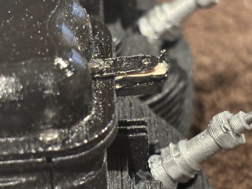
Now taking the mounting tab you made in the eyebrow section, attach it to the valve cover with the cheese head screw
Now trim the tabs down to just above the mounting tab as seen in this photo.
Now with flat black paint, let’s paint all the wood parts of the mount tab along with the tabs on the valve covers black this will help to hide all of it.
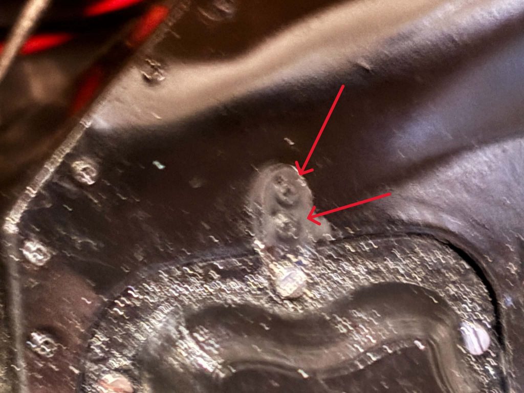
With the eyebrow in place, drill through the tab and eyebrow with a .028 bit and insert two 1m screws for each tab. Do not overtighten them.
Not the best photo but the arrow points out the screws, and they have been painted black to match the eyebrows.
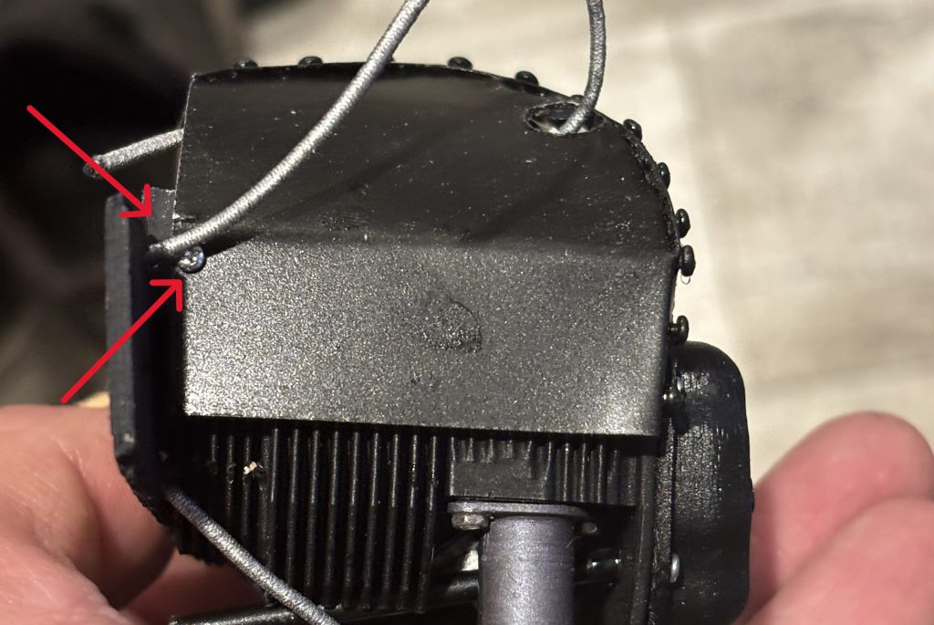
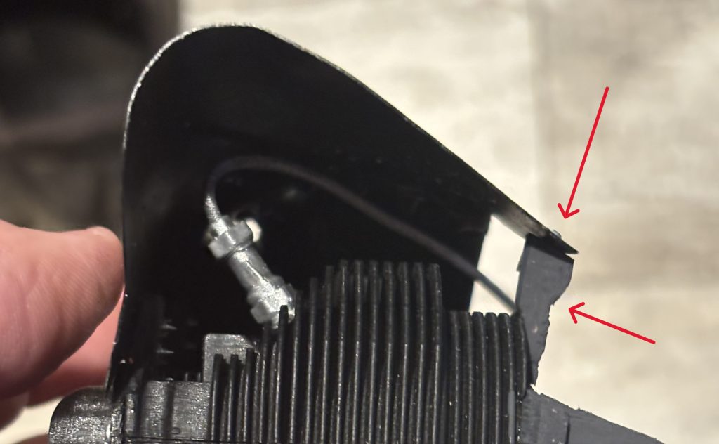
For the back side of the eyebrow, I like to use some scrap spruce stock and make a hard point on the back and the front of the eyebrow. I will paint them flat black to help hide them. Below points out the hard points. I use a #0 screw not supplied to attach the eyebrow.
This should be what your finished product looks like. For the dangling plug wire, they all need to be tucked toward the back. I recommend looking to see how your full-scale routes them and then fix them according. They can be glued with med CA.
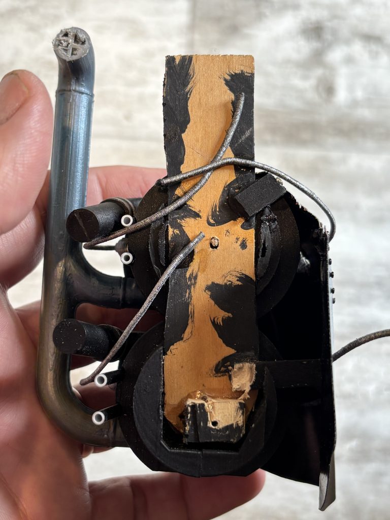
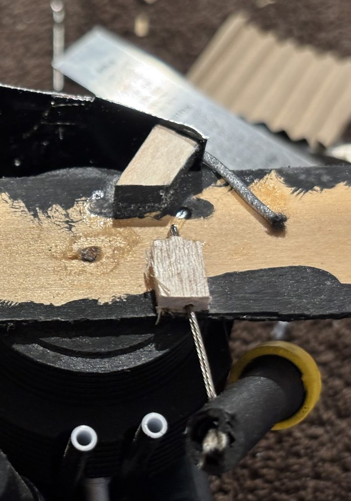
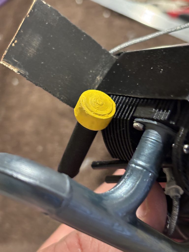
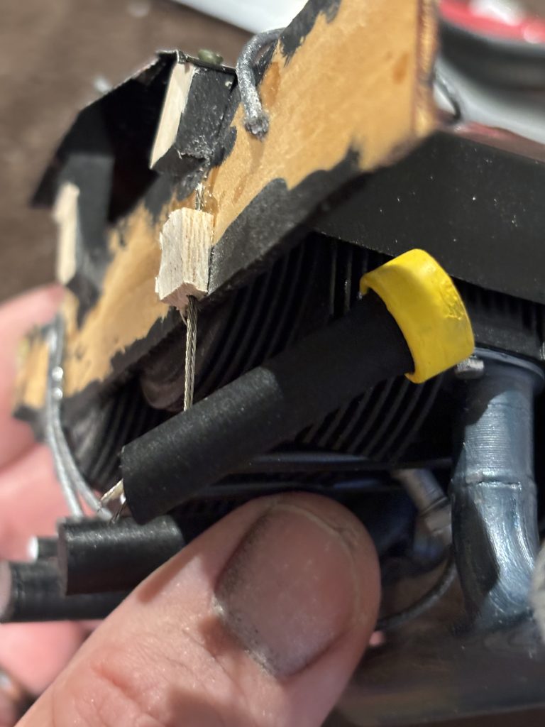
Now the oil cap. Most all I have seen have had a yellow cap and black tube, but paint to match your full scale. Glue the cap onto the tube. For mounting I use a small block of balsa glued to the mount and a small section doubled of control line wire. The photos will give you an idea how it’s mounted. I use med CA for all gluing.
Now to attach the scale muffler on the bottom. Using some scrap control line wire I doubled it. Plug a block of hard balsa to the cowl and use the wire through the muffler to the block and use med CA to attach it all.
Now to mount to the cowl. You may need to trim some of the intake tubes or other parts to clear your engine setup. Remember to touch up all paint if you must trim.
Now for a few finished shots
Hope you have enjoyed this build. Send me a few photos of your finished build. Have any questions or comments send me an email.